KTR Kupplungstechnik
GmbH
D-48407 Rheine
ROTEX
®
GS
Operating/mounting instructions
KTR-N
Sheet:
Edition:
45510 EN
13of36
15
Please note protection
mark ISO 16016.
Drawn: 15.10.12 Pz Replaced for: KTR-N valid from 08.02.12
Verified: 29.10.12 Pz Replaced by:
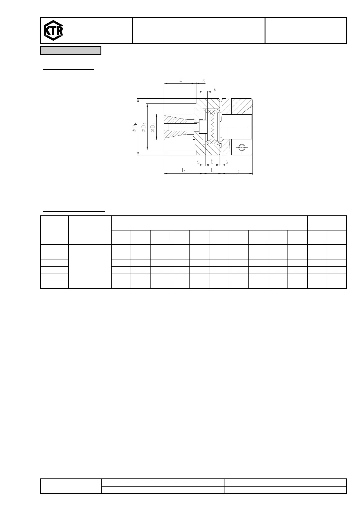
Expansion hubs
Illustration 9: ROTEX
®
GS, expansion hubs (type 9.0) with clamping hub
1)
Table 11: Dimensions
Size
Spider
(part 2)
Torques
[Nm]
Dimensions [mm]
Clamping
screw
D
1
D
2
D
H
l
1
l
4
l
5
l
6
E b s M T
A
9
Figures
see table 2
10 - 20 20 11 - 0 10 8 1,0
M4 2,9
12 10 20 25 19 14 1,5 2 12 10 1,0
M4 2,9
14 12 24 30 18,5
12,5
3 2 13 10 1,5
M4 2,9
19 20 35 40 28 20 1 0 16 12 2,0
M6 10
24 25 45 55 38 30 1 4 18 14 2,0
M8 25
28 35 55 65 44 36 1 5 20 15 2,5
M10
49
1) The expansion hub can be combined with other hub types being the opposite side, too. l
2
depends on the hub design. For further hub
designs see chapter 4.1.
2) For coupling selection – see ROTEX
®
GS catalogue
Transmittable friction torques for D
1
on request (depending on the hollow shaft).
Expansion hubs without keyway are not permissible for applications according to
DIN EN ISO 13849, part 2.