KTR Kupplungstechnik
GmbH
D-48407 Rheine
ROTEX
®
GS
Operating/mounting instructions
KTR-N
Sheet:
Edition:
45510 EN
25of36
15
Please note protection
mark ISO 16016.
Drawn: 15.10.12 Pz Replaced for: KTR-N valid from 08.02.12
Verified: 29.10.12 Pz Replaced by:
Assembly of Expansion Hubs (Type 9.0)
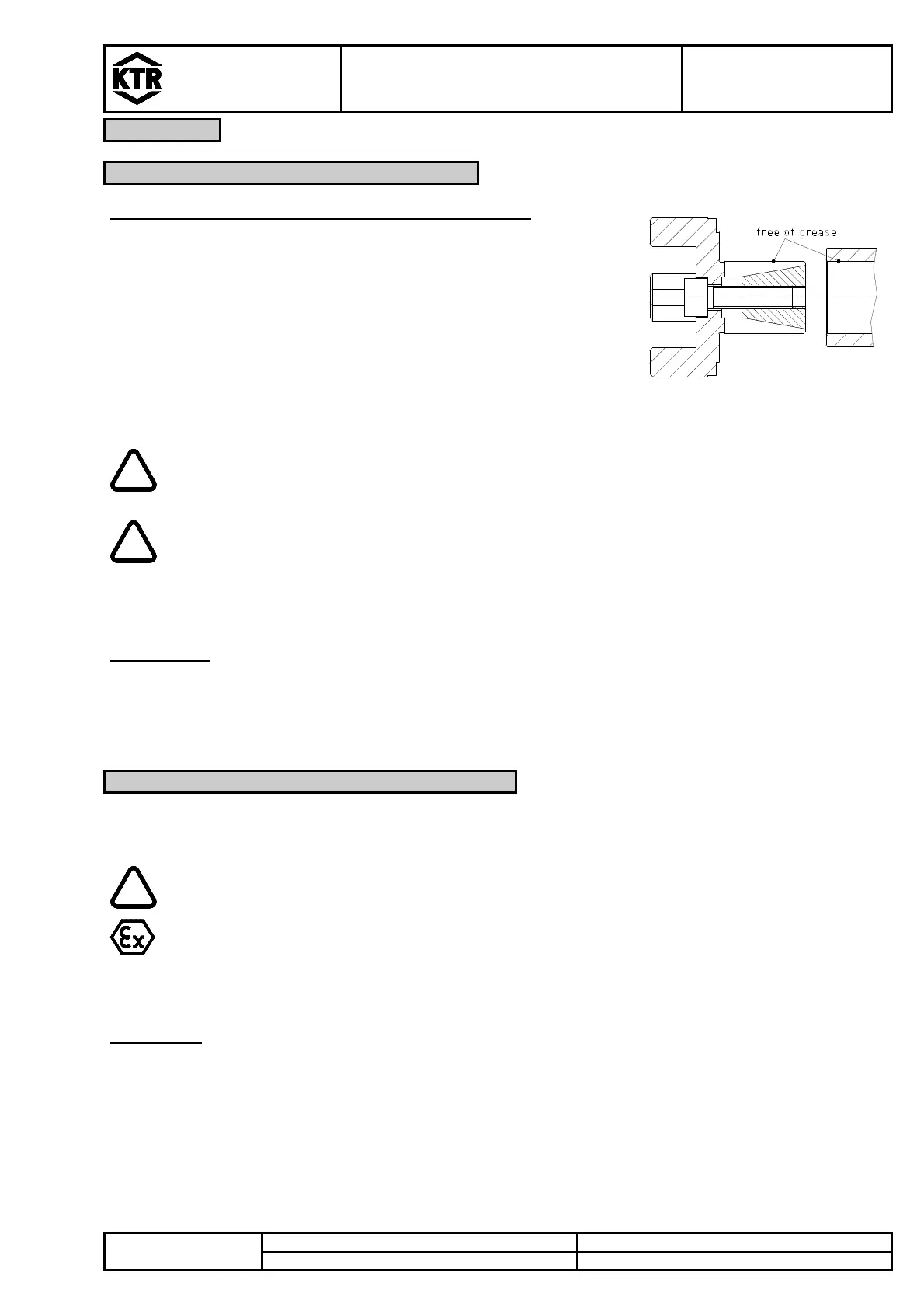
The following process should be noted for the
• Untighten clamping screw and clamping pin.
• Clean and degrease the internal diameter of the hollow shaft and the
outside contact surface of the expansion hub (see illustration 24).
• Insert the expansion hub along with clamping pin and clamping screw in
the hollow shaft. Tighten the clamping screw at the tightening torque
mentioned in table 11.
Illustration 24: Cleaning the
expansion hub and hollow shaft
The tightening torques apply for the figures mentioned
in table 11 only.
The frictionally engaged transmittable torques of the clamping hubs depend on the bore
diameter.
If the clamping screws are not tightened at the correct tightening torque, there is the danger
of
a) a fracture of the hub and plastic deformation with a too high tightening torque T
A
b) an early slipping, untightening of the screws with a too small tightening torque T
Disassembly:
Unscrew the clamping screw only slightly so that the clamping pin gets loosened. If the clamping pin did not
loosen, apply a light beat on the screw head. Afterwards remove the clamping screw fully.
Alignment of the Couplings
The displacement figures mentioned in table 13 and 14 provide for safety in order to compensate for external
influences like, for example, thermal expansion or sinking of basement.
In order to ensure a long lifetime of the coupling and avoid danger with the use in
hazardous areas, the shaft ends have to be aligned accurately. Please make absolutely sure
to observe the displacement figures indicated (see table 13 and 14). If these figures are
exceeded, the coupling will be damaged.
The more precisely the coupling is aligned, the higher is its service life.
For the use in hazardous areas for explosion class IIC (designation II 2GD c IIC T X) only the
displacement figures (see table 13 and 14) have to be carefully reviewed and adhered to.
Please note:
• The displacement figures mentioned in table 13 and 14 are maximum figures which must not arise in parallel.
If radial and angular displacements arise at the same time, the permissible displacement figures may only be
used proportionally.
• Please review by means of a metering clockwork, ruler or feeler gauge if the permissible displacement figures
mentioned in table 13 and 14 are observed.