KTR Kupplungstechnik
GmbH
D-48407 Rheine
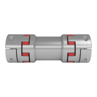
ROTEX
®
GS
Operating/mounting instructions
KTR-N
Sheet:
Edition:
45510 EN
20of36
15
Please note protection
mark ISO 16016.
Drawn: 15.10.12 Pz Replaced for: KTR-N valid from 08.02.12
Verified: 29.10.12 Pz Replaced by:
Subject to its typeROTEX
®
GS allows to axially plug in the coupling having assembled the hubs onto the shaft
journal. Consequently there is no need for subsequent screwing and the corresponding mounting holes in the
housing.
The pegs on the spider arranged reciprocally avoid a contact between the spider and the hubs over the full
surface. Observing the distance dimension E, the ability for displacement of the coupling is ensured in this way.All
teeth are chamfered on the face which allows a blind assembly. When the coupling hubs are combined with the
ROTEX
®
GS spider an axial mounting force is produced resulting from the flexible prestress of the star-shape
elastomer. This mounting force varies depending on the coupling size, the spider hardness and the machining
tolerances. The axial mounting force is compensated for after assembly of the hubs and consequently does not
mean any danger of axial load onto adjacent bearings.
The mounting force can be reduced by slightly greasing or oiling the elastomer or the hubs. For this purpose
please only use oils and greases on a mineral oil basis without any additives. Lubricants on a silicone basis
(e. g. OptimolOptisit WX) or vaseline have proven their worth, too.
STOP
The maximum permissible bore diameters d (see tables 1
to 11 in chapter 1 – Technical Data) must not be exceeded.
If these figures are not observed, the coupling may tear.
Rotating fragments may be hazardous.
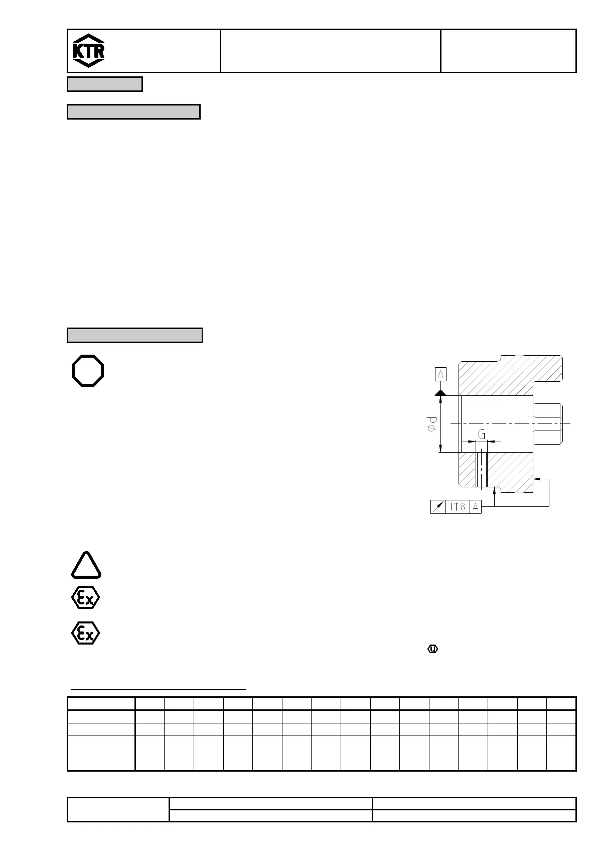
• If the hub bore is machined by the customer, the accuracy in
concentric running or run-out, respectively (see
illustration20) has to be observed.
• Please make absolutely sure to observe the figures for
Ød
max.
.
• Align the hubs carefully when machining the finish bore.
• Please use a setscrew according to DIN EN ISO 4029 with
cup point or an end plate to secure the hubs axially.
Illustration 20: accuracy in concentric
running or run-out
The buyer is responsible for all subsequently made machinings to unbored or pilot bored
and to finish machined coupling parts and spare parts. KTR does not assume any warranty
claims resulting from insufficient refinish.
KTR supplies unbored or pilot bored coupling parts and spare parts on explicit customer´s
request. These parts are additionally labelled with the symbol .
Table 12: SetscrewsDIN EN ISO 4029
Size 5 7 9 12
14
19
24
28
38
42
48
55
65
75
90
Dimension G
M2
M3
M4
M4
M4
M5
M5
M8
M8
M8
M8
M10
M10
M10
M12
Dimension t
2,5
3,5
5 5 5 10
10
15
15
20
20
20
20
25
30
Tightening
torque T
A
[Nm]
- - 1,5
1,5
1,5
2 2 10
10
10
10
17
17
17
40