KTR Kupplungstechnik
GmbH
D-48407 Rheine
ROTEX
®
GS
Operating/mounting instructions
KTR-N
Sheet:
Edition:
45510 EN
19of36
15
Please note protection
mark ISO 16016.
Drawn: 15.10.12 Pz Replaced for: KTR-N valid from 08.02.12
Verified: 29.10.12 Pz Replaced by:
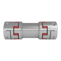
Components of ROTEX
®
GS Compact, clamping hubs
1 2 clamping hub (hub types 2.8 or 2.9)
2 1 spider
3 2 / 4 cap screwsDIN EN ISO 4762
Illustration 17: ROTEX
®
GS Compact, size 7 - 19 Illustration 18: ROTEX
®
GS Compact, size 24 - 38
Hub types 1.1, 2.0, 2.5, 2.8, 7.5 and 7.8 (without feather key) may only be used in category 3 and are
not permissible for applications according to DIN EN ISO 13849, part 2.
Selection of clamping hubs
With the use in explosion-proof areas the clamping hubs have to be selected in a way that the
difference between the peak torque of the machine including all operation parameters and the
frictionally engaged torque of the clamping ring hub is at least a service factor of s = 2.
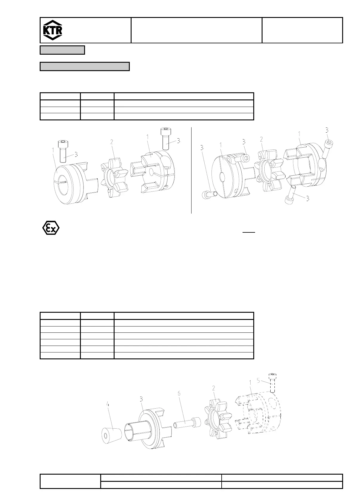
Components of ROTEX
®
GS, Expansion hubs
1
hub
2 1 spider
3 1 expansion hub
4 1 clamping pin for expansion hub
5
cap screws DIN EN ISO 4762
6 1 cap screws DIN EN ISO 4762
1)
The expansion hub can be combined with other hub designs being the opposite side, too, please note your dimension sheet.
Illustration 19: ROTEX
®
GS, expansion hubs