KTR Kupplungstechnik
GmbH
D-48407 Rheine
ROTEX
®
GS
Operating/mounting instructions
KTR-N
Sheet:
Edition:
45510 EN
18of36
15
Please note protection
mark ISO 16016.
Drawn: 15.10.12 Pz Replaced for: KTR-N valid from 08.02.12
Verified: 29.10.12 Pz Replaced by:
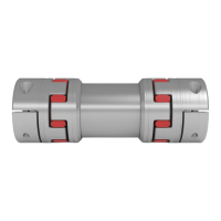
Components of ROTEX
®
GS, clamping ring hubs (types 6.0, 6.0 steel, 6.0 light and type 6.5)
1 2 clamping ring
2 2 clamping ring hub
3 1 spider
4
see table
5,6 and 7
cap screwsDIN EN ISO 4762
Illustration 15: ROTEX
®
GS, clamping ring hub
Selection of clamping hubs
With the use in explosion-proof areas the clamping hubs have to be selected in a way that the
difference between the peak torque of the machine including all operation parameters and the
frictionally engaged torque of the clamping hub is at least a service factor of s = 2.
Subject to the increased safety with the assembly (several screws are tightened) and the high
friction torque of the clamping ring hub, this design is permissible for applications according to
DIN EN ISO 13849, part 2.
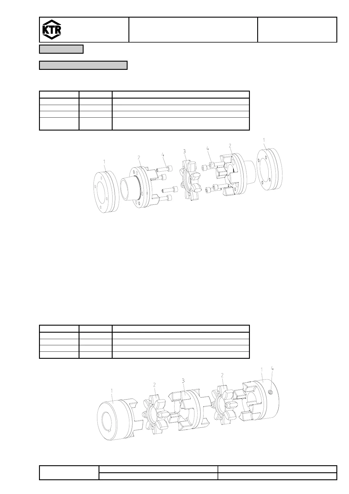
Components of ROTEX
®
GS, DKM
1 2 hub
2 2 spider
3 1 DKM spacer
4 2 setscrewDIN EN ISO 4029
Illustration 16: ROTEX
®
GS, DKM