KTR Kupplungstechnik
GmbH
D-48407 Rheine
ROTEX
®
GS
Operating/mounting instructions
KTR-N
Sheet:
Edition:
45510 EN
22of36
15
Please note protection
mark ISO 16016.
Drawn: 15.10.12 Pz Replaced for: KTR-N valid from 08.02.12
Verified: 29.10.12 Pz Replaced by:
Assembly of Clamping Hubs
2.6, 2.8,2.9, 7.5, 7.6, 7.8 and
The power transmission of ROTEX
®
GS clamping hubs (types 2.0, 2.5, 2.8, 7.5 and 7.8) is done frictionally
engaged. With types 2.1, 2.6, 2.9, 7.6 and 7.9 a feather key additionally provides for positive locking power
transmission.
The following process should be noted for the assembly:
• Clean and degrease the hub bore and the shaft.
• Slightly detach the clamping screw.
• Slip the hub onto the shaft. Please observe the dimension l
1
/l
2
.
• Tighten the clamping screws at the tightening torques mentioned in table 3.
For types 2.8, 7.5, 7.8 or 2.9, 7.6, 7.9 (with keyway) the screws have to be
tightened alternately at the tightening torques mentioned in table 3.
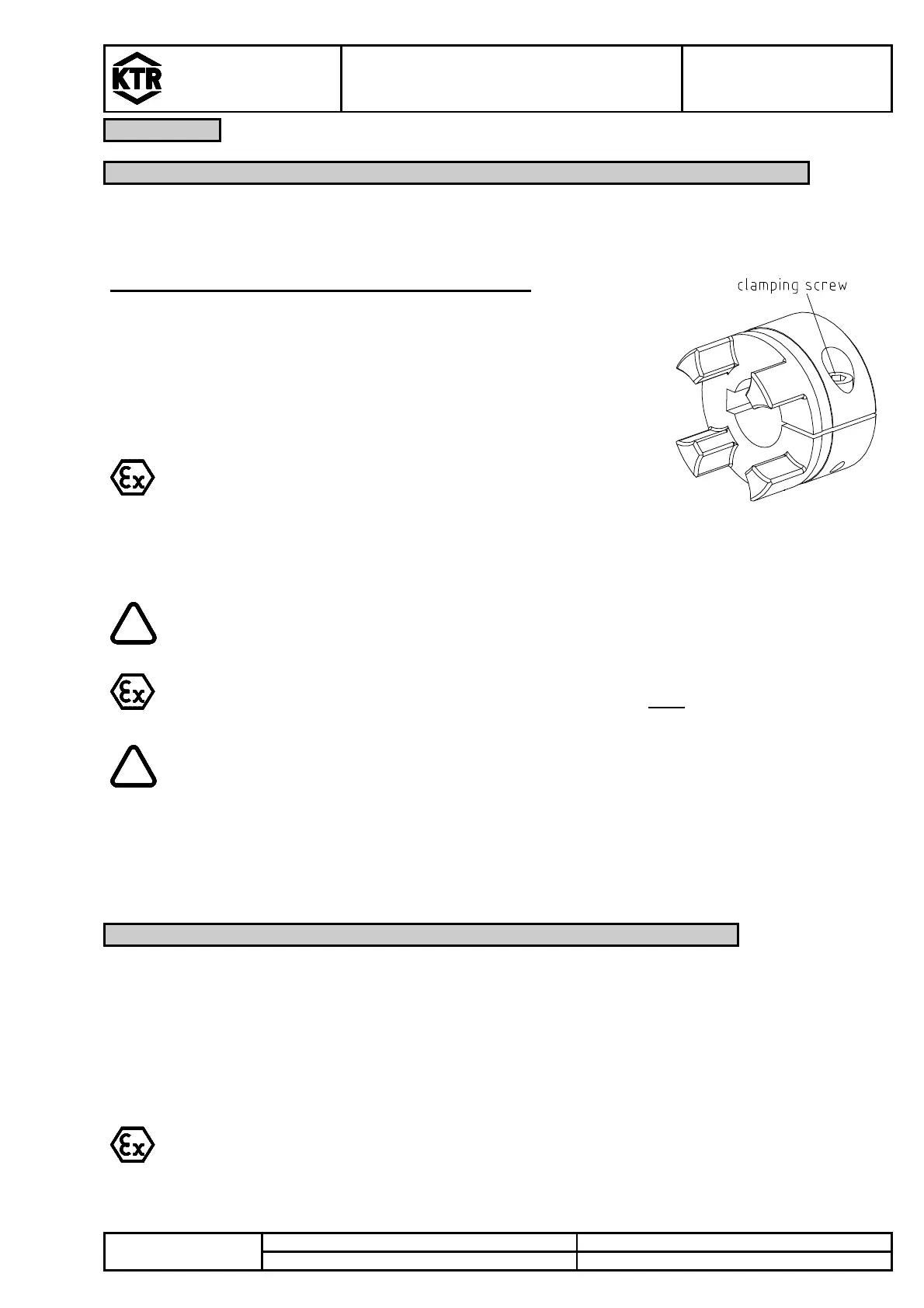
Illustration 21: Assembly clamping hub
Please note: types 2.8, 2.9, 7.5, 7.6, 7,8
or 7.9 have 2 clamping screws
For the applications in hazardous areas the setscrews to
fasten the hubs as well as all screw connections have to be
secured against self-slackening additionally, e. g. by glueing
with Loctite (medium-tight).
The frictionally engaged transmittable torques of the clamping hubs depend on the bore
diameter.
Hub types 2.0, 2.5, 2.8, 7.5 and 7.8 (without feather key) may only be used in category 3 and
are not permissible for applications according to DIN EN ISO 13849, part 2.
If the clamping screws are not tightened at the correct tightening torque, there is the danger
of
a) a fracture of the hub and plastic deformation with a too high tightening torque T
A
b) type 6.0: a fracture of the hubs/cams and plastic deformation with a too high tightening
torque T
A
c) an early slippling, untightening of the screws with a too small tightening torque T
Assembly of Clamping Ring Hubs
The power transmission of ROTEX
®
GS clamping ring hubs is frictionally engaged. The necessary surface
pressure is transmitted via the clamping ring with internal taper to the taper hub and consequently to the shaft.
The torques mentioned in tables 5 to 7 take into account a combination of fit H7/k6 from Ø55 G7/m6. With a
higher backlash of fit the torques mentioned in tables 5 to 7 are reduced.
The stiffness and dimensions of the shafts (here specifically hollow shafts) have to be selected in a way that
sufficient safety against plastic deformation is ensured. This may roughly be reviewed as per the following
criterion.
For the use in hazardous areas the setscrews/capscrews and setscrews to fasten the hubs
additionally have to be secured against slackening, e. g. by conglutinating with Loctite
(average joint strength).