KTR Kupplungstechnik
GmbH
D-48407 Rheine
ROTEX
®
GS
Operating/mounting instructions
KTR-N
Sheet:
Edition:
45510 EN
23of36
15
Please note protection
mark ISO 16016.
Drawn: 15.10.12 Pz Replaced for: KTR-N valid from 08.02.12
Verified: 29.10.12 Pz Replaced by:
Assembly of Clamping Ring Hubs
For clamping connections with hollow shafts the
required internal diameter of the hollow shaft d
iW
is
calculated based on the following formula:
[ ]
mm
R
p2R
dd
2,0p
W2,0p
iW
⋅−
⋅≤
Shearing stress on the internal shaft diameter for
hollow shaft:
2
2
W
W
tiW
mm/N
C1
p2
−
⋅
−≈σ
Shearing stress for solid shaft:
2
WtW
mm/Np−=σ
R
= proof stress of shaft material [Nmm
] d
= internal diameter of hollow shaft [mm]
p
= surface pressure hub/shaft [N/mm
] d = shaft diameter [mm]
C
= d
/ d
The required strength does not exist if the hollow shaft bore is bigger than the max. internal bore calculated or if
the shearing stress exceeds the yield strength of the material. For a detailed calculation please contact the KTR
engineering department.
• Clean the hub bore and shaft and review for dimensional accuracy,
afterwards lubricate with a thin-bodied oil (e. g. Castrol 4 in 1 or
KlüberQuietsch-Ex).
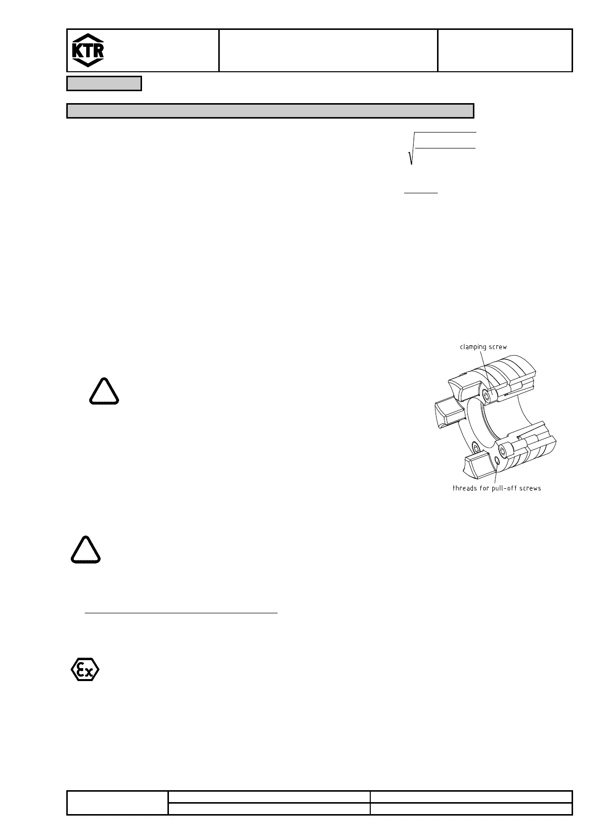
Illustration 22: Assembly of
clamping ring hub with clamping ring
Oils and greases containing molybdenum disulfide or
other high-pressure additives as well as internal
lubricants must not be used.
• Slightly detach the clamping screw and pull the clamping ring from the hub
only marginally to make sure that the clamping ring is loosened.
• Slip the clamping ring hub onto the shaft. The dimension L
3
should be
adhered to at least.
• Tighten the clamping screws evenly stepwise and crosswise to the
tightening torque mentioned in table 6 or 7. This process has to be
repeated until the tightening torque is reached for all clamping screws.
If the clamping screws are not tightened at the correct tightening torque, there is the danger
of
a) a fracture of the hub and plastic deformation with a too high tightening torque T
A
b) an early slipping, untightening of the screws with a too small tightening torque T
• Assembly of the clamping ring hub 6.0 light:
Tighten the clamping screws evenly stepwise and crosswise at 1/3 or 2/3 tightening torque T
A
, respectively
(see table 5) until the ring gets in contact. Afterwards tighten the screws at the tightening torque mentioned in
table 5 one after another.
For the applications in hazardous areas the setscrews to fasten the hubs as well as all
screw connections have to be secured against self-slackening additionally, e. g. by glueing
with Loctite (medium-tight).
Selection of clamping hubs
With the use in explosion-proof areas the clamping hubs have to be selected in a way that
the difference between the peak torque of the machine including all operation parameters
and the frictionally engaged torque of the clamping hub is at least a service factor of s = 2.