KTR Kupplungstechnik
GmbH
D-48407 Rheine
ROTEX
®
GS
Operating/mounting instructions
KTR-N
Sheet:
Edition:
45510 EN
4of36
15
Please note protection
mark ISO 16016.
Drawn: 15.10.12 Pz Replaced for: KTR-N valid from 08.02.12
Verified: 29.10.12 Pz Replaced by:
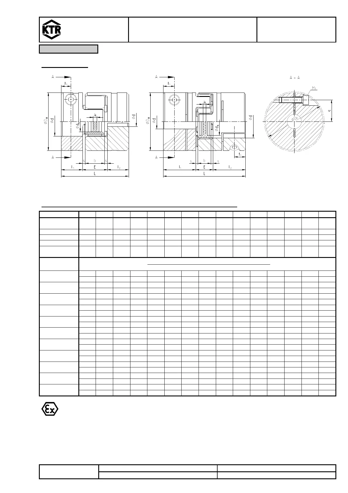
Clamping hubs
Illustration 3: ROTEX
®
GS, size 5 – 14(type 2.0) Illustration 4: ROTEX
®
GS, size 19 - 75(type 2.5)
Table 3:Torques and surface pressure of clamping hubs types 2.0 / 2.5
Size 5 7 9 12 14 19 24 28 38 42 48 55 65 75 90
Clamping
screw M
M1,2
M2
M2,5
M3
M3
M6
M6
M8
M8
M10
M12
M12
M12
M16
M20
Dimension t
2,5
3,5
5,0
5,0
5,0
11,0
10,5
11,5
15,5
18 21 26 33 36 40
Dimension e 3,5
5,0
7,5
9,0
11,5
14,5
20 25 30 32 36 42,5
45 51 60
Dimension ØD
11,4
16,5
23,4
27,5
32,2
46 57,5
73 83,5
93,5
105
119,5
124
147,5
192
Tightening
torque T
[Nm]
- 0,37
0,76
1,34
1,34
10,5
10,5
25 25 69 120
120
120
295
580
Bore Ø
Transmittable torque of Clamping hub [Nm]
Surface pressure [N/mm
2
]
Ø2
-
Ø3
- 0,84
71,02
Ø4
- 0,91
2,07
3,65
4,48
43,02
68,51
109,9
134,9
Ø5
- 0,97
2,18
3,81
4,64
29,50
46,15
73,5
89,5
Ø6
1,04
2,28
3,98
4,81
23,6
21,85
33,65
53,3
64,4
139,3
Ø7
1,10
2,39
4,14
4,97
24,3
17,06
25,90
40,8
48,9
105,2
Ø8
1,17
2,50
4,31
5,14
25,0
32,4
13,83
20,73
32,5
38,7
82,8
131,0
Ø9
2,61
4,48
5,30
25,7
33,1
17,09
26,6
31,6
67,2
105,7
Ø10
2,72
4,64
5,47
26,3
33,8
74,3
14,42
22,4
26,4
55,9
87,3
171,3
Ø11
2,83
4,81
5,64
27,0
34,4
75,5
12,40
19,2
22,5
47,4
73,6
143,9
Ø12
4,97
5,80
27,7
35,1
76,7
89,1
16,7
19,4
40,8
63,1
122,9
105,9
For the applications in hazardous areas the setscrews to fasten the hubs as well as all screw
connections have to be secured against self-slackening additionally, e. g. by glueing with Loctite
(medium-tight).
Clamping hubs type 2.0 and 2.5 without keyway are not permissible for applications according to
DIN EN ISO 13849, part 2.