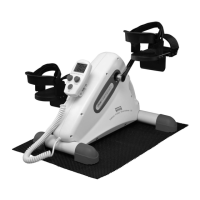
The device described in this manual is the Kübler Sport Oxycycle III Pedal Exerciser, a rehabilitation and exercise aid designed for both active and passive (motor-assisted) use. It is primarily intended to facilitate leg and arm exercises, promoting circulation, muscle strength, and flexibility. The compact design allows for use in various settings, such as on a table for arm exercises or on the floor for leg exercises.
Function Description:
The Oxycycle III Pedal Exerciser operates with an electric motor, providing assistance during exercise, which is particularly beneficial for users with limited mobility or those undergoing rehabilitation. It features two main modes of operation: active mode and passive mode.
In active mode, the user powers the pedals, and the device offers adjustable resistance. This mode is suitable for users who can actively pedal and wish to build strength and endurance. The resistance levels can be set from 0 to 5 using a dedicated resistance control knob. It is crucial to ensure the speed control knob is in the "off" position before adjusting the resistance. Once the resistance control knob is turned on, the device operates exclusively in active mode, and the speed control knob should not be engaged.
In passive mode (motor-assisted), the device's motor moves the pedals, allowing users to experience a gentle, continuous motion without expending significant effort. This mode is ideal for passive rehabilitation, improving joint mobility, and stimulating circulation. Users can set the desired speed using the speed control knob. Similar to active mode, the resistance control knob must be set to the "off" (0 level) position before engaging the speed control knob for passive exercise. The device incorporates an overload protection mechanism. If excessive force is applied or pedaling occurs at speeds significantly higher than the motor's set speed, the motor will temporarily stop to prevent damage. This protective shutdown lasts for 2-3 seconds before the motor automatically restarts. If the motor overload situation persists and the motor stops and restarts 10 times, it will cease operation completely to prevent equipment damage. In such an event, a "STOP" sign will flash on the controller screen, accompanied by an 8-second alarm, prompting the user to turn the speed control knob to the "off" position and then restart the device.
The device is equipped with a wired controller that allows users to manage its functions, including adjusting resistance or speed, and monitoring exercise parameters. The controller is connected to the main unit via a coiled cable, providing flexibility in placement during use.
Usage Features:
The Oxycycle III Pedal Exerciser is designed for ease of use, with clear instructions for setting up and operating the device.
- Power Connection: The device requires a power cord to be plugged into an electrical outlet to function. Operating the device without being plugged in will cause damage.
- Mode Selection: Users can choose between active and passive modes based on their exercise needs and physical capabilities.
- Resistance Adjustment (Active Mode): A resistance control knob allows for precise adjustment of exercise intensity, with levels ranging from 0 to 5. This knob should only be adjusted when the speed control knob is off.
- Speed Adjustment (Passive Mode): A speed control knob enables users to set the desired motor-assisted pedaling speed. This knob should only be adjusted when the resistance control knob is off (level 0).
- Overload Protection: The integrated overload protection system safeguards the motor from damage due to excessive force or speed discrepancies, ensuring the longevity of the equipment.
- Controller Interface: The wired controller provides an intuitive interface for managing exercise settings and receiving feedback, such as overload warnings.
Maintenance Features:
The manual provides detailed, step-by-step instructions for various maintenance and repair procedures, indicating that certain components are designed to be replaceable. This approach supports the device's longevity and allows for troubleshooting common issues. Key maintenance features include:
- Controller Bracket Removal and Installation: The controller bracket, which holds the wired controller, can be easily removed and reinstalled using a screwdriver to detach/attach bolts and nuts. This facilitates access to internal components or replacement of the bracket itself.
- Foot Pedal Removal and Installation: The foot pedals are marked "R" for right and "L" for left to ensure correct reinstallation. They can be removed using a wrench by turning the pedal shaft in specific directions (counter-clockwise for the right pedal, clockwise for the left pedal) until loose. Installation involves threading the pedal shaft into the crank and tightening with a wrench.
- Crank Removal and Installation: The cranks, also marked "R" and "L," require a more involved removal process. This includes removing a plastic cap with pliers, detaching a bolt with an Allen wrench, and then using a crank puller to remove the crank from the motor axle. Reinstallation follows the reverse steps, ensuring the plastic cap is tightened in the counter-clockwise direction.
- Cover Removal and Installation: The device's covers (right and left) are secured by multiple bolts and can be removed with a screwdriver. This provides access to the internal mechanisms for repairs or component replacement. Reinstallation involves aligning the covers and securing them with the appropriate bolts.
- Motor Replacement: The manual outlines how to remove and replace the motor. This involves disconnecting red and black wires from the Power Control Board (PCB) using pliers, removing six bolts from the main frame with a screwdriver, and then detaching the motor. When installing a new motor, it's crucial to ensure the bolt under the motor axle is attached with the wire onto the main frame and to reconnect the wires correctly to the PCB.
- Rotor Replacement: The rotor, including its flying wheel, can be replaced. This involves removing the motor cover (secured by three bolts with a screwdriver) and then detaching the rotor. The manual highlights the presence of plastic washers (one on the motor side, three on the cover side) that must be correctly placed during reassembly to ensure proper function.
- Power Control Board (PCB) Replacement: The PCB is fixed in place by six supports. To remove it, pliers are used to pinch the head of the supports, allowing the board to be pulled out. Installation involves aligning the new PCB with the support holes on the main frame and snapping it into place.
- Controller Wire Disconnection and Reconnection: The controller's wires, including the cable connector to the PCB and the wire connecting to the sensor, can be disconnected and reconnected carefully. This is essential for replacing the controller or accessing other internal components.
These detailed maintenance instructions suggest that the Oxycycle III Pedal Exerciser is designed for maintainability, allowing users or technicians to perform component replacements and extend the life of the device.