5.1
ENGINE
G17oo·G1800·G1900·G20oo
WSM.10831
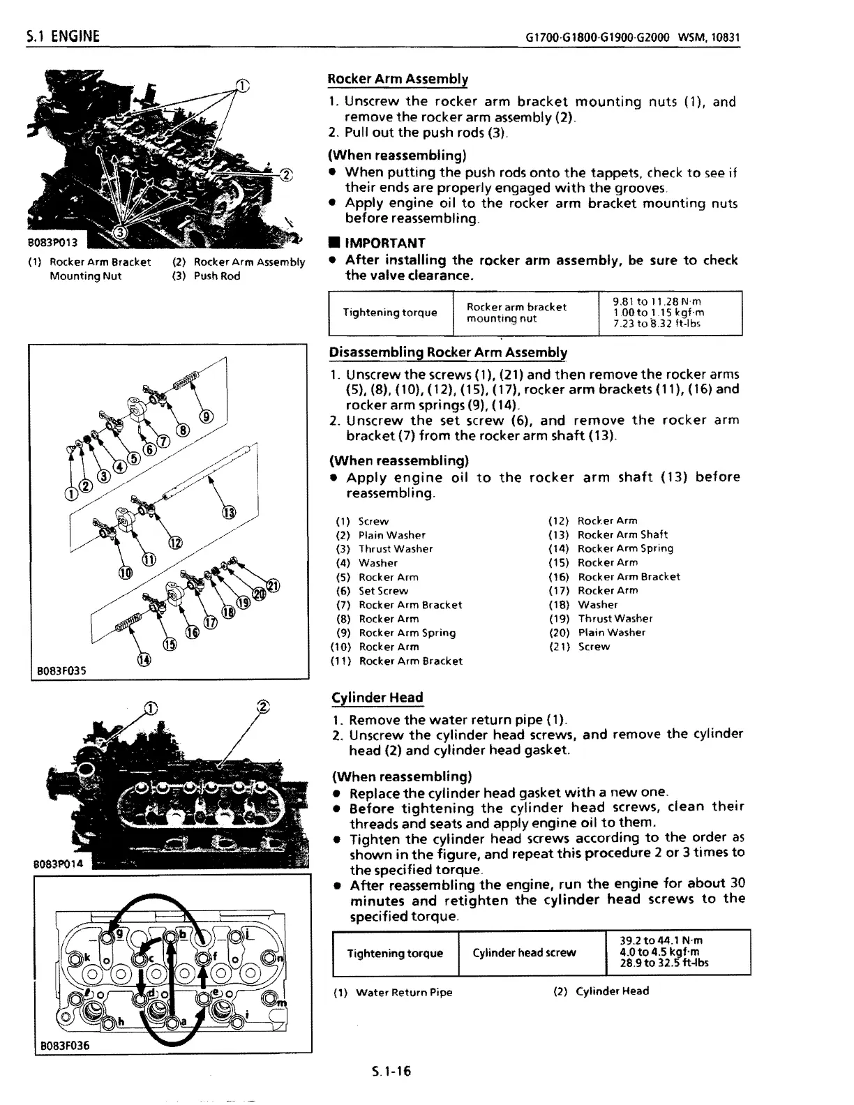
Rocker
Arm
Bracket
(2) Rocker
Arm
Assembly
Mounting
Nut
(3) Push Rod
Tightening
torque
Cylinder head screw
39.2to44.1
N·m
4.0
to
4.5 kgf'm
28.9
to
32.5 ft-lbs
Rocker
Arm
Assembly
1.
Unscrew
the
rocker
arm
bracket
mounting
nuts (1), and
remove
the
rocker arm assembly (2).
2.
Pull
out
the
push rods (3).
(When
reassembling)
•
When
putting
the
push rods
onto
the
tappets, check
to
see
if
their
ends are properly engaged
with
the
grooves.
•
Apply
engine
oil
to
the
rocker arm bracket
mounting
nuts
before reassembling .
• IMPORTANT
•
After
installing
the
rocker arm assembly, be sure
to
check
the
valve clearance.
Tightening
torque
Rocker arm
bracket
mounting
nut
9.81
to
11.28
N'm
1.00
to
1.15
kgf·m
7.23tolU2
ft-Ibs
Disassembling Rocker
Arm
Assembly
1.
Unscrew
the
screws (1), (21) and
then
remove
the
rocker arms
(5), (8), (10), (12), (15), (17), rocker
arm
brackets (11), (16) and
rocker arm springs (9), (14).
2.
Unscrew
the
set screw (6),
and
remove
the
rocker
arm
bracket (7)
from
the
rocker arm
shaft
(13).
(When
reassembling)
•
Apply
engine
oil
to
the
rocker
arm
shaft
(13)
before
reassembling.
(1)
Screw
(12)
Rocker Arm
(2) Plain
Washer
(13)
Rocker Arm
Shaft
(3)
Thrust
Washer
(14)
Rocker
Arm
Spring
(4)
Washer
(15)
Rocker
Arm
(5) Rocker
Arm
(16) Rocker
Arm
Bracket
(6) Set Screw
(17)
Rocker Arm
(7)
Rocker
Arm
Bracket
(IS)
Washer
(S) Rocker
Arm
<19}
Thrust
Washer
(9) Rocker
Arm
Spring
(20)
Plain Washer
(10)
Rocker
Arm
(21)
Screw
(11 )
Rocker
Arm
Bracket
Cllinder
Head
1.
Remove
the
water
return
pipe (1).
2.
Unscrew
the
cylinder head screws,
and
remove
the
cylinder
head (2) and cylinder head gasket.
(When
reassembling)
• Replace
the
cylinder head gasket
with
a
new
one.
•
Before
tightening
the
cylinder
head
screws,
clean
their
threads and seats and apply
engine
oil
to
them.
• Tighten
the
cylinder head screws according
to
the
order
as
shown
in
the
figure,
and repeat
this
procedure 2 or 3 times
to
the
specified
torque.
•
After
reassembling
the
engine,
run
the
engine
for
about
30
minutes
and
retighten
the
cylinder
head
screws
to
the
specified
torque.
(1)
Water
Return
Pipe
(2)
Cylinder
Head
S.1-16
 Loading...