GENERAL
GL6000A-AU-B, GL6000D-AU-B,GL9000A-AU-B, GL9000D-AU-B, WSM
G-24
Valve Clearance
• The valve clearance must be checked and adjusted when
engine is cold.
1. Remove the head cover, the glow plugs and the timing window
cover on the flywheel housing.
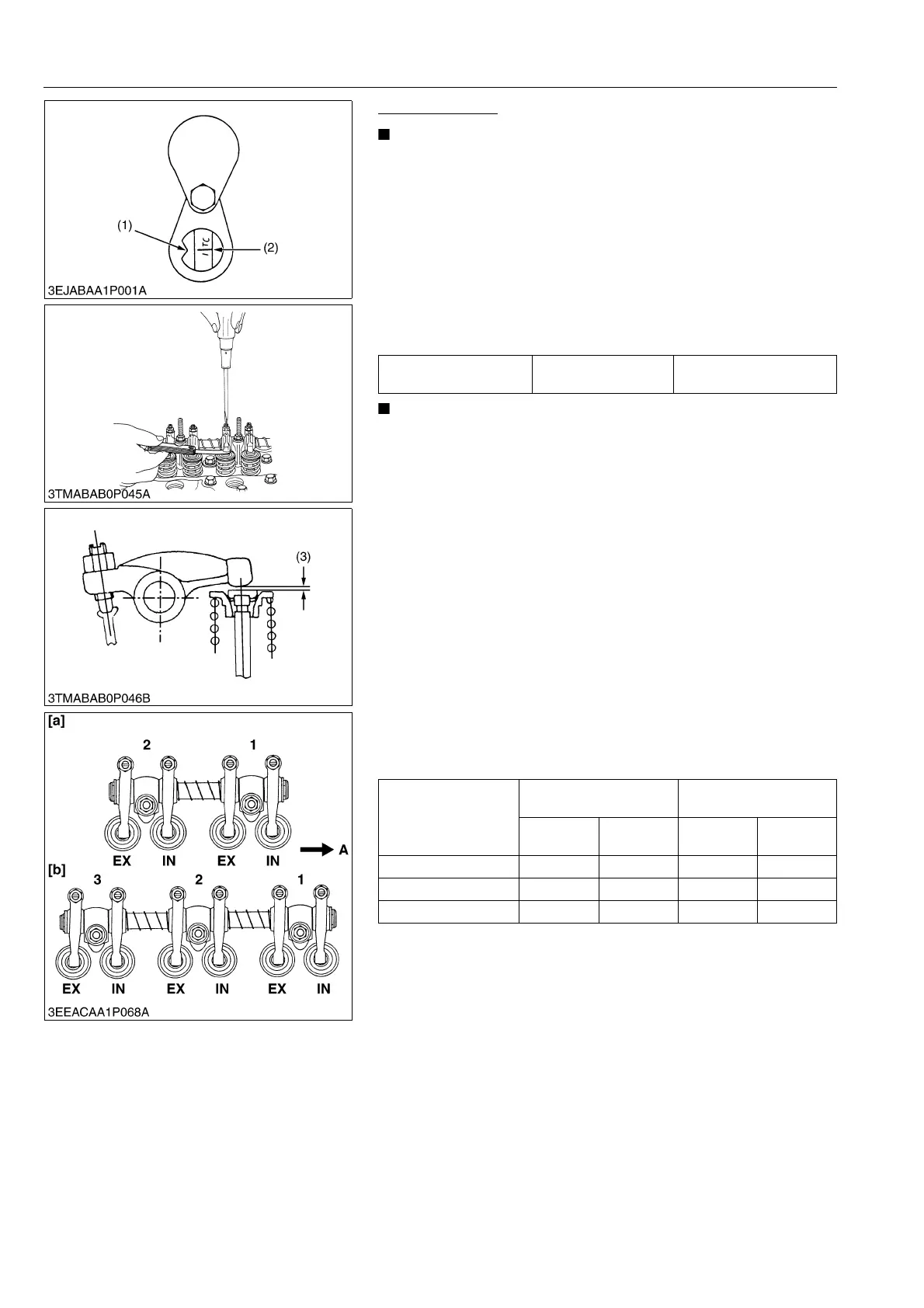
2. Align the 1TC mark line (2) on the flywheel and center of timing
window (1) so that the No. 1 piston comes to the compression
or overlap top dead center.
3. Check the following valve clearance marked with "" using a
feeler gauge.
4. If the clearance is not within the factory specifications, adjust
with the adjusting screw.
• The "TC" marking line on the flywheel is just for No. 1
cylinder. There is no TC marking for the other cylinders.
• No. 1 piston comes to the top dead center position when
the TC marking is aligned with center of timing window on
flywheel-housing. Turn the flywheel 0.26 rad (15°)
clockwise and counterclockwise to see if the piston is at
the compression top dead center or the overlap position.
Now referring to the table below, readjust the valve
clearance. (The piston is at the compression top dead
center when both the IN. and EX. valves do not move; it is
at the overlap position when both the valves move.)
• Finally turn the flywheel 6.28 rad (360°) and align the TC
marking line and the center of timing window. Adjust all the
other valve clearance as required.
• After turning the flywheel counterclockwise twice or three
times, recheck the valve clearance, firmly tighten the lock
nut of the adjusting screw.
• The sequence of cylinder numbers is given as No. 1, No. 2
and No. 3 starting from the gear case side.
: When No.1 piston is at the compression top dead center position.
: When No.1 piston is at the overlap position.
9Y1211607GEG0036US0
Intake and exhaust valve
clearance (cold)
Factory specification
0.145 to 0.185 mm
0.00571 to 0.00728 in.
Adjustable Cylinder
Location of Piston
GL6000A-AU-B
GL6000D-AU-B
GL9000A-AU-B
GL9000D-AU-B
Intake
valve
Exhaust
valve
Intake
valve
Exhaust
valve
No.1
No.2
No.3 – –
(1) Timing Window
(2) 1TC Mark Line
(3) Valve Clearance
A: Gear Case Side
[a] GL6000A-AU-B, GL6000D-AU-B
[b] GL9000A-AU-B, GL9000D-AU-B
 Loading...