INSTALLATION & OWNER’S MANUAL
p. 1 of 15
The contents of this envelope are the property of the owner.
Be sure to leave with the owner when installation is complete.
V5008
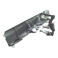
Kubota RTV
72” Snow Blade
Do not attempt to install or operate this
plow until you read and understand all
warnings and instructions in this manual or
on the plow. Failure to read all warnings
and instructions could lead to serious injury
or death.
Curtis Cabs, blades and general accessories
exceed the vehicle's rated capacity including
from the vehicle's rated capacity and never
brochures. Deduct the accessory's total weight
Curtis accessory weights are listed in product
add additional weight to the base vehicle. All
driver and passenger.
ADDED
WEIGHT
These instructions are only valid for attachment to RTV-X900,
RTV-X1100C, RTV-X1120, RTV-XG850, and RTV-X1140 utility vehicles.
Note: Front Heavy Duty Springs (V5218) or Heavy Duty Spring Damper
Assembly (V5219) are required for RTV-X900, RTV-X1120, and RTV-XG850.
Heavy duty springs come standard on RTV-X1140 model.
For RTV-XG850, installation of K7591-97900 grill guard kit is required.
Approximate Installation Time: 1-2 hours
IMPORTANT: Please read the installation instructions
thoroughly before beginning. Installation of any item is
easier if the vehicle is clean and free of debris.
manual p/n: 77700-05199 (V5008P1)
(Rev. D) 11/20/2018
California Health and Safety Proposition 65 Warning: This product may contain
chemicals known to the state of California to cause cancer and birth defects or other reproductive harm.