HYDRAULIC SYSTEM
L3540-II, L4240-II, L5040-II, L5240-II, L5740-II , WSM
8-M7
4. THREE POINT HITCH HYDRAULIC SYSTEM
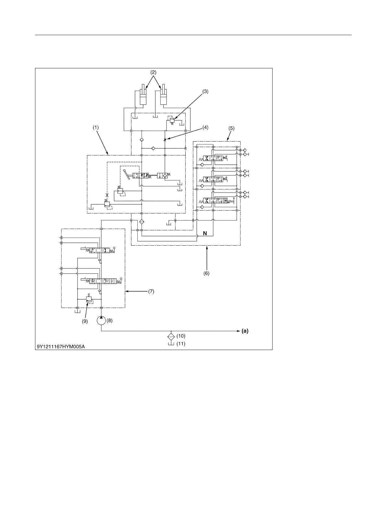
[1] THREE POINT HITCH HYDRAULIC CIRCUIT
1. When the engine is started, the hydraulic pump 1 (8) is rotated to draw oil from transmission case (11) through
the suction pipe.
Supplied oil is filtered by the hydraulic oil filter cartridge (10).
2. Filtered oil is forced out by the hydraulic pump to the auxiliary control valve (5) through the front loader control
valve (7).
3. With the auxiliary control valve (5) in neutral position, oil is channeled from "N" port to the control valve (1).
4. The hydraulic system has a relief valve (9) which restricts the maximum pressure in the circuit.
The hydraulic cylinders (2) have a cylinder safety valve (3) to relieve shock pressure due to heavy implement
bounce.
5. The control valve (1) is actuated by the mechanical linkage for "Position control function".
9Y1211167HYM0007US0
(1) Position Control Valve
(2) Hydraulic Cylinder
(3) Cylinder Safety Valve
(4) Lowering Speed Adjusting
Valve
(5) Auxiliary Control Valve
(6) Rear Hydraulic Block
(7) Front Loader Control Valve
(8) Hydraulic Pump 1
(9) Relief Valve
(10) Oil Filter Cartridge
(11) Transmission Case
(a) To Power Steering
Controller
N: N Port
 Loading...


