EasyManua.ls Logo

Kuhse KEA 201 SPL - User Manual

Kuhse KEA 201 SPL
26 pages
Print Icon
To Next Page IconTo Next Page
Loading...
_________________________________________________________________________________
Alfred Kuhse GmbH
Phone: +49 4171-798-0
kuhse@kuhse.de
Changes without further notice reserved.
An der Kleinbahn 39, D-21423
Winsen (lu(
Fax +49 4171-798-117
www.kuhse.de
Service Manual
for product: KEA 201 SPL:
Power Control Unit for Emergency and
Peak Load Gensets with overlapping Synchronisation
File: SA_KEA 201 SPL_EN_Ver 2016-07-01 (replaces Version 2014-12-19)
_____________________________________________________________________________________
1. Design
The control unit is incorporate into the front door of the switchboard. When installed, the front meets the
protection class IP 44. The two rows of LEDs are marked with interchangeable labels. The relay units
are mounted on the mounting plate and linked to the control unit in the door with the supplied cable.
The control unit has an optical fibre and a USB interface for the connection of a PC. Only one of them can
be used at a time
1.1. Parameterisation
With the parameterisation software PARAWIN, the following settings (password-protected) and analogue
readouts are possible.
1. Additional Interface CAN
2. Additional Parameters
3. Alarm Remote Erasure
4. Alarms
5. Analogue Inputs
6. Analogue Outputs
7. Battery Monitor
8. CAN 0
9. Frequency Controller at isolated Operation
10. Generator Current Monitor
11. Generator Voltage Monitor
12. Hardware
13. Internal Synchroniser
14. J1939 engine management
15. J1939 Hide analogue values
16. Load Controller
17. Mains Voltage Monitor
18. Modem
19. Power Factor Controller
20. ProMerk. programmable Flags
21. Reference Load Regulation
22. Relay and Indicator Functions
23. Speed Monitoring and Control
24. Sprinkler Operation
25. Starting and Stopping
26. Transfer Mains – Generator
27. VDE-AR-N 4105 Protection for Parallel Operation
28. Voltage Controller
Parameterisation can also be performed at the display.

Table of Contents

Question and Answer IconNeed help?

Do you have a question about the Kuhse KEA 201 SPL and is the answer not in the manual?

Summary

Design

1.1. Parameterisation

Details on parameterization software PARAWIN and available settings.

Analogue Readouts

1.2. Analogue Readouts

List of signals and values monitored by the control unit.

Amendments

2.1. Version History

Records of changes and document versions over time.

Safety Instructions

4.1. Regulations and Instructions

Adherence to VDE regulations and prevention of risks.

4.2. Installation and Commissioning

Guidance for qualified personnel on installation and commissioning.

4.3. Connections

Precautions for correct device connection to prevent damage.

4.4. Battery and Supply voltage

Instructions for battery disconnection, grounding, and supply voltage.

4.5. Inductors

Requirements for fitting coils with reverse diodes and suppressor elements.

Connection

5.1. Operating the Display

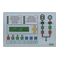
Navigating and modifying parameters using the display interface.

5.2. Setting the Display Contrast

Procedure for adjusting the display contrast using specific buttons.

PIN Number, Ident-Number

6.1. PIN and IDENT-Number Management

Access and modification of PIN and IDENT-NUMBER for parameterization.

Parameterisation Menu Structure

7.1. Menu Group Overview

Structure of parameterization menu groups and functions.

Alarm Monitoring

8.1. Description

Overview of alarm control, types, and configuration options.

8.2. Alarm Announcing and Acknowledgement

Procedure for acknowledging alarms and status indicators.

8.3. Explanation of Alarms

Detailed explanations for various alarm types and their causes.

Mains Failure Protection in Parallel Operation

9.1. Monitoring Deviations in Voltage and Frequency

Monitoring mains voltage and frequency deviations against previous values.

9.2. Vector Shift

Measurement of vector shift for detecting mains failures.

9.3. Sealing the Setpoints

Procedure for sealing setpoints using a jumper on the PCB.

Mains Reference Load Control Operation

10.1. Operation Description

Control operation based on mains reference load and generator output.

10.2. High and Low-Tariff Operation

Setting different parameters for high and low-tariff periods.

Peak Load Operation Mode

11.1. Mode Description

How the genset operates in peak load mode.

Mains Operators Load Levels

12.1. Load Level Settings

Specifying maximally allowed load levels via terminal inputs.

Enabling Mains Parallel Operation

13.1. Description

Conditions for enabling mains parallel operation based on frequency and voltage.

13.2. Setpoint for Power

Predefining power setpoints for mains parallel operation.

Mains Recovery in Peak Load Operation

14.1. Recovery Conditions

Conditions for starting after a mains failure in peak load operation.

Power Control

15.1. Frequency Range 50.2 - 51.5 Hz

Power control behavior within specific frequency ranges.

Controlling Reactive Power

16.1. Reactive Power Setpoints

Setting reactive power based on VDE-AR-N-4105 characteristic curve or fixed factor.

Sprinkler Operation

17.1. Sprinkler Functionality

Functions provided for electric sprinkler pump operation.

Connection of Relay Unit RZ 071-D

18.1. Alarm and Control Inputs (Terminals 1-14)

Description of terminal functions for alarm signals and general control inputs.

18.2. Feedback and Operation Mode Terminals (Terminals 15-26)

Functions of feedback signals and operation mode selection terminals.

Flags for Alarm Inputs and Relays

18.3. Power Control and Special Function Terminals (Terminals 27-29)

Functions of terminals for peak load power control and charging dynamo.

19.1. Alarm and Relay Flag Codes

List of flags for alarm inputs and relays with corresponding codes.

Technical Data

19.2. Terminal Function Flags and Other Flags

Mapping of terminal functions and system states to flags.

20.1. KEA Controller Specifications

Dimensions, protection class, temperature, and supply voltage of the KEA controller.

20.2. Analogue Inputs and Outputs

Details on analogue I/O, voltage, frequency, and current monitoring.

20.3. Relay Unit RZ 071-D Specifications

Specifications for the RZ 071-D relay unit, including dimensions and relays.

20.4. Relay unit RZ 071-E (Optional) Specifications

Specifications for the optional RZ 071-E relay unit.

Serial Interfaces

20.5. Serial Interfaces

Details on optical fibre, USB, and CAN bus serial interfaces.

20.6. Connection to Other Systems (Optional)

Options for connecting to other systems via KNG gateway.

Diagrams

21.1. Response Diagram for Thermal Overload

Graph of thermal overload response delay vs. preset current.

21.2. Connection Diagram, RZ-071-D

Wiring diagram for the RZ-071-D relay unit and its terminals.

21.3. Connection Diagram, RZ-071-E (Optional)

Wiring diagram for the optional RZ-071-E relay unit.

21.4. Connection Diagram, KEA 201 SPL

Wiring diagram for the KEA 201 SPL controller.

21.5. Connections, Analogue Inputs

Schematics for connecting analogue input sensors.

21.6. Door Cross Section of KEA, Frontview

Diagram showing the front view and dimensions of the KEA door.

Controller PCB with Jumper for Sealing Setpoints

21.7.1. PCB Layout and Jumper Function

Illustration of the controller PCB, highlighting the setpoint sealing jumper.

Drilling Template, Scale 1:1 - print without scaling!

22.1. Mounting Hole Dimensions

Template with dimensions for drilling mounting holes.

Kuhse KEA 201 SPL Specifications

General IconGeneral
BrandKuhse
ModelKEA 201 SPL
CategoryControl Systems
LanguageEnglish