Do you have a question about the Kunft WQP12-9260C and is the answer not in the manual?
Details the voltage and frequency requirements for the appliance.
Specifies the acceptable range for water supply pressure.
Indicates the maximum allowed supply water temperature.
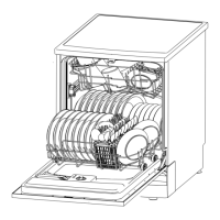
Explains the water intake process, including softening and air breaker storage.
Details how water is pumped through spray arms during the washing cycle.
Describes the regeneration process involving the softener and resin tank.
Step-by-step instructions for removing the Printed Circuit Board.
Explains the electromagnetic operation of the inlet valve.
Lists common failure modes and associated error codes for the inlet valve.
Provides specifications such as voltage, resistance, and power for the inlet valve.
Step-by-step guide to physically access and remove the inlet valve.
Procedure to test the electrical resistance of the inlet valve.
Steps to inspect the mechanical aspects of the inlet valve, including the filter.
Describes the operation of the drain pump, driven by a permanent magnet motor.
Lists common faults and error codes associated with the drain pump.
Provides specifications for the drain pump, including voltage, resistance, and performance.
Step-by-step guide to physically access and remove the drain pump.
Procedure to test the electrical resistance of the drain pump's motor coil.
Steps to inspect mechanical issues like the non-return valve and drain hose.
Illustrates the heater's connection with thermostats and pressure switch.
Lists common failure modes and error codes for the heating element.
Provides specifications for the heater, including voltage, power, and thermostat temperatures.
Step-by-step guide to physically access and remove the heating element.
Procedure to measure the resistance of the heater coil and thermostat.
Explains the asynchronous motor operation with capacitor for the washing pump.
Lists common faults and error codes related to the washing pump.
Provides specifications for the washing pump, including resistance and performance.
Step-by-step guide to physically access and remove the washing pump assembly.
Procedure to test the electrical resistance of the washing pump's motor coils.
Steps to inspect mechanical issues like pump assembly looseness or vane wheel.
Explains the diaphragm mechanism and its role in water level control.
Illustrates the NTC thermistor's position within the appliance's sump.
Describes the NTC's function in measuring water temperature.
Step-by-step guide to access and remove the NTC thermistor.
Procedure to test the NTC's resistance at various temperatures.
Shows the flowmeter's integration with the air breaker.
Explains how the flowmeter measures water intake using an impeller and pulses.
Step-by-step guide to access the flowmeter by removing the air breaker.
Procedure to test the flowmeter's electrical pulse output.
Illustrates the placement of electronic and mechanical Aquastop hoses.
Explains the two-layer mechanism and fault detection for both types.
Step-by-step guide to access and remove the safety hose assembly.
Procedure to test electrical resistance of the electronic Aquastop hose.
Describes potential faults like moisture absorption causing self-lock.
Instructions on initiating the diagnostic test program.
Explains how to identify error codes via buzzer alarms and indicator flashes.
Details causes and behavior for E1 error (water filling time).
Details causes and behavior for E3 error (heating time).
Details causes and behavior for E4 error (overflow).
Details causes and behavior for E6 error (thermistor open circuit).
Details causes and behavior for E7 error (thermistor short circuit).
| Brand | Kunft |
|---|---|
| Model | WQP12-9260C |
| Category | Dishwasher |
| Language | English |