Chapter 5 - Disassembly/Assembly Pr'ocedures
5.1
5.2
5.3
5.4
5.5
5.6
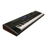
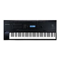
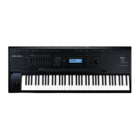
Kurzweil250
5.1.1
Kurzweil 250 Enclosure
5.1.2 Kurzweil250
Slide Chassis
5.1.3
CPU Board
5.1.4
CGP Board
5.1.5
Channel Board
5.1.6
Audio Board
Front Panel Assembly
5.2.1
Accessing the Front Panel Assembly
Figure
5.1
5.2.2
Removing the Front Panel Assembly
5.2.3
Closing the Front Panel Assembly
Keyboard Assembly
5.3.1 Accessing the Keyboard
5.3.2
Accessing the Keyswitch Board Assembly
5.3.3 Keyswitch Maintenance
5.3.4 Replacing a Keyswitch Board Assembly
Figure 5.2
Mod Levers
5.4.1 Accessing the Mod Levers
5.4.2 Removing the Mod Lever Pots
Figure 5.3
5.4.3 Calibrating the Mod Levers
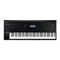
Kurzweil
250X
5.5.1 Kurzweil 250X Enclosure
Kurzweil RMX
250 and 225
5.6.1
5.6.2
5.6.3
5.6.4
5.6.5
5.6.6
5.6.7
5.6.8
Front Panel Assembly
Accessing the Front Panel Assembly
Inner Chassis Assembly
Figure 5.4
CPU Board
Replacing RMX Engine EPROMs
CGP Board
Power
Supply Assembly
Channel Board
Audio Board
Kurzweil
250
Service Manual, Chapter 5
5
-1
5-2
5-2
5-2
5-3
5-3
5-4
5-4
5-5
5-5
5-6
5-6
5-7
5-7
5-7
5-8
5-9
5-10
5-10
5-10
5-10
5-11
5-12
5-12
5-13
5-13
5-13
5-14
5-14
5-15
5-15
5-15
5-15
5-16
5-16
 Loading...
