Programming Examples
Example 4
19-8
This can still be a little harsh on the high end when you play with high attack velocities. One
way to smooth it out would be to go back to the ALG page, select a lowpass filter for the F2
block, and adjust its cutoff frequency to about F# 6. This is done by pressing EDIT when the F2
block is selected, then selecting the Adjust parameter and changing the value with any data
entry method.
errR®rrterrR®rrterrR®rrterrR®rrtYrrR®rrty
dPITCH|gkSHAPERgkLOPASSgkPANNERG;AMP|||GH
cvvvvvvbcvvvvvvbcvvvvvvbcvvvvvvbNvvvvvvbn
That’s it for the SHAPER example; we’ll continue with this program to describe the PANNER.
You’ll notice that in Algorithm 13, PANNER is the only value available for the F3 block. The
PANNER function takes a single signal from the sound engine, and splits it into two. These are
referred to as the upper and lower wires. The upper and lower wires pass independently into
the final Amp block, and from there to the audio outputs.
The parameters on the control input page for the PANNER let you distribute the signal between
the upper and lower wires. You can send the signal all to the lower wire (an Adjust value of-
100%), all to the upper wire (100%), or anywhere in between. This in itself won’t necessarily
change the pan position of the current layer. It works in tandem with the Pan parameter on the
layer’s OUTPUT page.
When a layer uses an algorithm that contains the PANNER function, you always have two
wires going through the final Amp and to the audio outputs. Consequently, on the layer’s
OUTPUT page, there are parameters to assign the output pair and pan position of each wire.
When you have one wire panned hard left, and the other hard right, changing the parameters
on the PANNER control input page will enable you to move the layer’s pan position in
realtime. The closer a layer’s output is to the center of the stereo field, the less effective the
PANNER function will be.
The first step in our PANNER example, therefore, will be to select the OUTPUT page. Select the
Pan parameter for the upper wire, and set it all the way to the right. Select the Pan parameter
for the lower wire and set it all the way to the left.
Now you can select the F3 POS page, and program it to move the sound around. First try
changing the value of the Adjust parameter. You should hear the sound move to the left when
the value is negative, and to the right when it’s positive. Set it back to 0%, then select the Src1
parameter. Select LFO1 as the value, then select the Depth parameter and set it to 100%.
Now select the Src1 parameter again, and press EDIT (or use the more soft button locate the
LFO button, then press it). You will now see the LFO page. Set the MnRate parameter for LFO1
to a value of 0.1 Hz. Set the MxRate parameter to a value of 2.00 Hz, and the RateCt parameter
to Data. Leave the Shape parameter set to Sine. You should hear the sound shift slowly from left
to right as the LFO cycles. You can adjust the speed of the shift with your MIDI controller’s data
slider (or a programmable control set to MIDI 06).
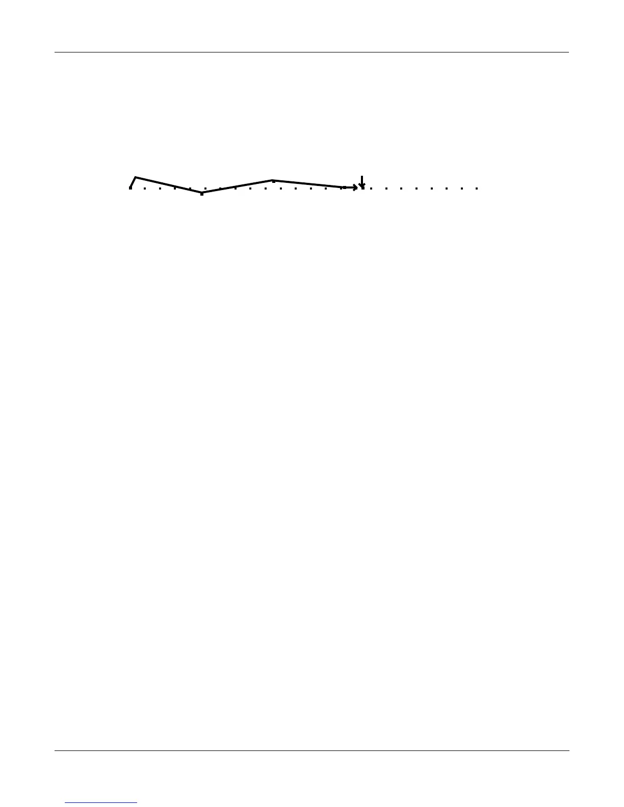
EditProg:ENV2|||||||[1/1]||<>Layer:1/1||
Att1:Att2:Att3:Dec1:Rel1:Rel2:Rel3:Loop:
0.10|0.82|0.86|1.04|0s|||0s|||0s|||Off||
51%||-23%|42%||0%|||0%|||0%|||0%|||Inf||
||||||||||||||||||||||||||||||||||||||||
||||||||||||||||||||||||||||||||||||||||
||||||||||||||||||||||||||||||||||||||||
<more||AMPENV|ENV2|||ENV3|||ENVCTL|more>
 Loading...