16-2
DSP Functions
Introduction to Algorithm Programming
functions you insert into the algorithm. The algorithm simply lays a framework that determines
how the DSP functions interact.
Once you know which algorithm youÕre going to work with, youÕll assign various DSP
functions to each of the stages of the algorithm. These stages, as you recall, are represented by
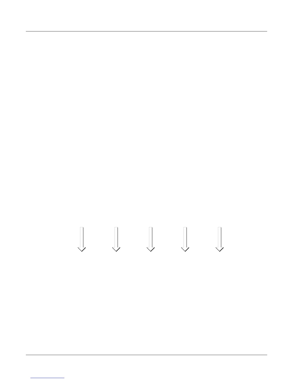
the rectangular blocks you see on the ALG page. The arrows pointing down at the blocks
represent control inputs that affect the behavior of the DSP functions. For each arrow, thereÕs a
page of parameters controlling some aspect of the DSP functionÕs behavior. Every DSP function
has at least one control input; several have two or three.
The ALG page is where you select algorithms and assign DSP functions to the algorithmÕs
various stages. To assign a DSP function, move the cursor to select the stage you want to modify,
then use any data entry method to scroll through the list of available DSP functions for that
stage. YouÕll normally hear the effect of each selection as soon as you make it. If you donÕt hear a
difference, itÕs because the functionÕs control parameters arenÕt set to signiÞcant values. Once
you adjust some of these parameters, the function will have a noticeable effect on the sound.
Keep in mind that not all DSP functions are available at every stage of every algorithm.
When you have each stage of the current algorithm set up to your liking, you can begin to
program the control inputs of each DSP function. This is done by selecting the control-input
page(s) for the currently selected DSP function, and adjusting the parameters on the page. There
are two ways to select the control-input pages: you can move the cursor to select the DSP
function you want to tweak, and press
Edit
. The selected DSP functionÕs control-input page will
appear (if itÕs a multi-stage DSP function, its Þrst control-input page will appear). Or you can
use the soft buttons to select the pages. The
PITCH
soft button always selects the pitch
control-input page, since the Þrst stage of every algorithm is invariably the pitch control. The
F1
Ð
F4
soft buttons select the control-input pages corresponding to the remaining four arrows,
which point down at the subsequent four variable control inputs.
Figure 16-1 Input Control for DSP Functions
Each control-input page contains several parameters, which affect some aspect of the behavior
of the DSP function named on the top line of the page. Most of these parameters are the common
DSP control parameters; for a review, see
Common DSP Control Parameters
on page 6-14.
The possibilities are truly enormous, given the number of different combinations of functions
you can assign to any particular layer (not to mention multi-layer programs, each layer of which
has its own algorithm). You can create completely new sounds just by tweaking the parameters
on the control-input page for a single DSP function. When you begin adjusting these
EditProg:ALG|||||||||||||||<>Layer:1/1||
||||||||||||||||||||||||||||||||||||||||
||||||||||||||||||||||||||||||||||||||||
errR®rrte11231111112311111123114errR®rt|
dPITCH|gkHIFREQ|STIMULATOR|||||0kAMP||gh
CVVVVVVBCVVVVVVVVVVVVVVVVVVVVVVBCVVVVVB|
||||||||||||||||||||||||||||||||||||||||
<more||F1|FRQ|F2|DRV|F3|AMP|F4|AMP|more>
F1
FREQUENCY
CONTROL
PARAMETERS
PITCH
CONTROL
PARAMETERS
F2
DRIVE
CONTROL
PARAMETERS
F3
AMP
CONTROL
PARAMETERS
F4
FINAL AMP
CONTROL
PARAMETERS
 Loading...