the cylinder, the cold water supply pressure and the
flow rate available at the supply to the system.
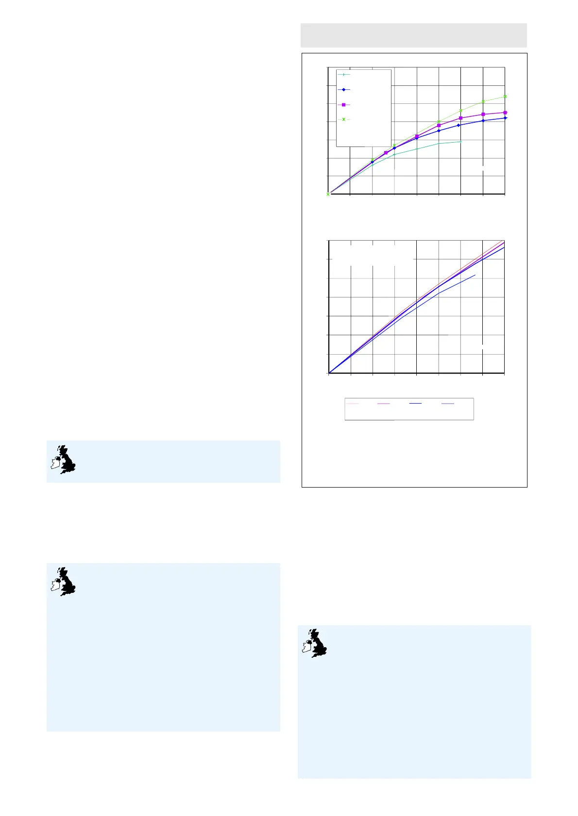
5.3 For design purposes the graphs in Figure 3
show the relationship between:
• flow available
• mains supply pressure, and
• the maximum hot water flow rate out of the
system
(1)
.
(1) Flow characteristics shown in the graphs reflect the worst
combination of cold water control components that may
be installed (see Detail Sheet 2).
5.4 The hot/cold mixed flows are for draw-off
temperatures of 40°C (assume 60% at 60°C and
40% at 10°C).
Heat-up, re-heating and hot water draw-off
temperature
5.5 The heat-up and re-heat times are comparable
with conventional systems of a similar size
supplying hot water.
5.6 The immersion heater will heat the stored
water from 15°C to 60°C in the time listed in
column A of Table 3.
5.7 The amount of water that can be drawn off
within 10°C of the set temperature is listed in
column B of Table 3, the mean temperature of 70%
of the water drawn off immediately after reaching
60°C in column C, and the time taken to re-heat
the stored water to 60°C in column D.
Temperature control
5.8 The thermostat wired to the immersion
heater is satisfactory for controlling the
temperature of the stored water.
Pressure control
5.9 The pressure control valve is satisfactory for
controlling the pressure of the water supplied from
the water mains or other suitable potable supply.
Insulation
5.10 The system is provided with adequate
insulation to satisfactorily limit the energy loss
from the stored water and meets the
requirements described in the national Building
Regulations:
England and Wales
Approved Document L1
Scotland
Regulation 22, Standard J3.4
Northern Ireland
Technical Booklet F, Paragraph 3.3.
5.11 The heat loss of each system while
maintaining the temperature of the stored water at
65°C is shown in Table 4.
Figure 3 Flow rates
Connections
5.12 The system is designed to be connected to
copper tube to BS EN 1057 : 1996, using
conventional plumbing fittings (see Table 1 for
details of connection sizes and threads). The
connections are of adequate size.
6 Safety
Excessive temperature — Prevention of explosion
— Safe discharge of hot water
6.1 The safety devices provided to ensure
that the temperature of the stored water will
not exceed 100°C, and safeguard the
operation of the system, are:
• the combined temperature and pressure relief
valve, and
• the non-self-resetting thermal cut-out fitted to the
system and wired to the immersion heater.
6.2 The system has a safety warning label
attached to the storage cylinder, bearing an
explanation of the action to be taken in the case of
0
10
20
30
40
50
60
70
0
10
20 30 40 50 60
70
80
2 bar
3 bar
4 bar
8 bar
Static supply pressures
of incoming water
supply
flow available (lmin ) at entry to system
–1
flow out (lmin ) of the system
–1
hot only
¾" valves
0
10
20
30
40
50
60
70
01020304050
60 70 80
flow available at entry to the system(lmin )
–1
8 bar 4 bar 3 bar 2 bar
Static supply pressures of incoming water supply
flow out (lmin ) of the system
–1
• Flow rates shown apply to situations where the supply is capable of supplying an
adequate dynamic pressure.
• The graph represents the results of tests carried out by the BBA.
• Where static water supplies are less than 1 bar, consult Kwikot Limited or the BBA.
• Flow rates shown for mixed hot/cold water assume that the cold supply is not
taken from the balanced connection of the pressure reducing valve
Notes
hot/cold mixed
mixed water at 40ºC, mixed from
60% hot water at 60ºC and
40% cold water at 10ºC
¾" valves
 Loading...