3 Labelling/marking
The system carries a label(s) bearing the
information set out in Table 2 and is supplied with
a comprehensive installation/user manual.
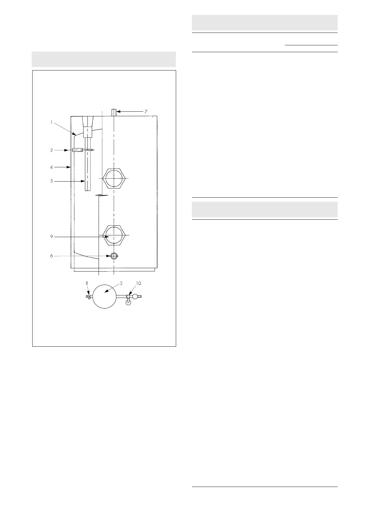
Figure 1 General layout
Key to Figure 1
1 Storage cylinder manufactured from 2 mm thick steel.
2 Combined temperature and pressure relief valve (see Detail Sheet 2).
Factory fitted.
3 Expansion vessel.
4 Insulation (PU foam) covered by white, epoxy-coated steel outer casing.
5 Corrosion protection magnesium alloy anode.
6 Cold water feed (¾” BSP male).
7 Hot water draw-off (¾” BSP female).
8 Drain valve to BS 2879 : 1980.
9 Immersion heater.
10 Cold water control valves (see Detail Sheet 2):
line strainer
check valve
expansion valve
pressure reducing valve.
Table 1 Storage capacities and dimensions
Manufacturer’s system
reference
150 210
Storage capacity (litres) 150 210
Cylinder size (mm)
height 1036 1382
diameter 450 450
overall height 1090 1436
overall diameter 525 525
Weight of cylinder (kg)
empty 50 67
full 200 277
Expansion vessel capacity (litres) 16 16
Connection sizes
mains water supply to control valves —
(mm) compression fitting 22 22
balanced cold water draw-off —
(mm) compression fitting 22 22
cold water inlet to storage cylinder —
(BSP inches male) ¾ ¾
hot water draw-off — (BSP inches male) ¾ ¾
expansion valve discharge —
(BSP inches male) ½ ½
temperature and pressure relief valve
discharge — (BSP inches female) ½ ½
Immersion heater
rating at 240 V (kW) 3 3
heater length (mm) 280 280
Anode length (mm) 370 480
Table 2 Labels
General
1 The BBA identification mark incorporating the number of this Certificate.
2 The system uses BEAB (British Electrical Approvals Board) approved
electrical controls.
3 UKWFBS (United Kingdom Water Fittings Byelaws Scheme) list number.
4 Manufacturer’s name.
5 Product code number.
6 Serial number.
7 The system is an unvented system.
Design
1 Maximum water supply pressure (bar).
2 Operating pressure (bar).
3 Expansion valve setting (bar).
4 Immersion heater(s) — Power/voltage — Type/BS/Length.
5 Storage capacity (litres).
6 Weight of unit — full (kg).
7 Expansion vessel charge pressure (bar).
Safety warnings/conditions
1 Installation to be carried out only by a
competent person.
2 The removal/replacement of any component to be carried out only by a
competent person
using components supplied by the Certificate holder in
accordance with their instructions.
3 Any malfunction of the system such as that resulting in discharge of water
from the expansion valve or the combined temperature and pressure relief
valve to be reported to a
competent person
after switching off the heat
source and prior to any further use of the system.
4 The installation of the system is subject to approval under the Building
Regulations, Water Byelaws and Regulations, the Health and Safety at
Work etc Act 1974 (where appropriate) and the Health and Safety at
Work (Northern Ireland) Order 1978 (where appropriate).
Installer
(1)
details
1 Space for:
(a) Name
(b) Address
(c) Telephone number
(d) Completion date
(e) Registration No ....
2 A declaration that installation has been in accordance with BBA
Certificate
No 96/3253 with space for signature of the installer
(1)
.
CE mark
1 The system complies with the Low Voltage Directive 73/23/EEC.
2 The system when installed correctly will comply with the Electromagnetic
Compatibility Directive 89/336/EEC.
3 A CE mark applied to these products by the manufacturer relates only to the
Low Voltage and Electromagnetic Compatibility Directive. In the opinion of
the BBA, the application of the CE mark does not infer compliance with the
requirements of the applicable Building Regulations.
(1) The installer must meet the definition of a
competent person
as defined in section 15.2.
2
 Loading...