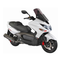
Do you have a question about the KYMCO Xciting 500i and is the answer not in the manual?
Details on bore, stroke, compression, displacement, spark plug, and idle speed.
Tire sizes for front and rear.
Details on battery, headlights, tail/brake lights, turn signals, position lights, and fuses.
List of Keihin system components with their full names and abbreviations.
Procedure to verify the Check Engine Lamp (CELP) functionality.
Understanding blink counts to identify specific failure codes.
Diagnostic Trouble Codes (DTCs) related to TPS, MAP, WTS, Tilt Switch, O2 Sensor, and Injector.
Diagnostic Trouble Codes (DTCs) for ignition coil, fuel pump, O2 heater, ISC, AICV, and CPS.
Step-by-step instructions to reset diagnostic trouble codes.
Steps to reset the TPS and ISC components.
Introduction to the diagnostic tool's screen, buttons, and indicators.
Checking TPS/ISC status at closed throttle using the diagnostic tool.
Checking TPS/ISC status at fully open throttle using the diagnostic tool.
Steps for connecting the Fi diagnostic tool to the vehicle.
Connecting the diagnostic tool and verifying software version.
Using the diagnostic tool to view and navigate the DTC list.
Accessing and viewing historical diagnostic trouble codes.
Steps to clear diagnostic trouble codes using the tool.
Exploring different data analysis screens on the diagnostic tool.
Details on screens showing engine temp, ISC, and cut-out voltage.
Procedure for resetting and installing the ISC component.
Instructions for MAP sensor removal, installation, and inspection.
Inspection of TPS and the need for resetting after component changes.
Detailed steps for cleaning the throttle body and its butterfly valve.
Procedure for inspecting the fuel pump relay's continuity.
Instructions for removing and installing the fuel pump and its O-ring.
Procedure to check fuel output pressure and its importance for starting.
Detailed procedure for safely removing the fuel injector.
Instructions for installing the fuel injector with proper O-ring and tab alignment.
Procedure to clean fuel injectors, addressing output and injection time issues.
Measuring voltage at different tilt angles for the tilt switch.
Standard resistance values for the water temperature sensor at various temperatures.
Measuring the resistance of the O2 sensor for proper function.
Overview of specifications for various Keihin EMS components like ECU, MAP, TPS, etc.
Location and operational description of the ABS indicator light on the meter.
Details on ABS operation, limitations, and precautions for safe use.
Visual guide to the location of major ABS system parts.
Numbered list identifying ABS components shown in the diagram.
Connecting the Fi diagnostic tool and performing initial setup.
Understanding the diagnostic tool's screen layout and navigation menus.
Display of ECU model and version details on the diagnostic tool.
Navigating the DTC Inspection menu for active, occurred, and history codes.
Displaying specific DTCs and the procedure to clear them.
Interpreting data from diagnostic tool screens like speed, voltage, and ECU status.
Procedure for removing and installing front and rear wheel speed sensors.
Caution regarding potential damage to ABS ECU or Hydraulic Unit during removal.
Notes for replacing the Hydraulic Unit and torque specifications for bolts and nuts.
Checking the resistance of front and rear wheel speed sensors.
| Fuel System | Electronic Fuel Injection |
|---|---|
| Front Suspension | Telescopic fork |
| Rear Brake | Single disc |
| ABS | Yes |
| Width | 800 mm |
| Seat Height | 800 mm |
| Wheelbase | 1, 580 mm |
| Fuel Capacity | 12.8 liters |
| Top Speed | 160 km/h |
| Engine Type | Liquid-cooled, 4-stroke, 4-valve, SOHC |
| Displacement | 499cc |
| Transmission | CVT |
| Rear Suspension | Double swing |
| Front Brake | Dual Discs |


