5-4.DCVoltageMeasurement
DANGER
●
Nevermakemeasurementonacircuitinwhich
voltage over DC600V exists to avoid getting
electricalshock.
●
Do not make measurement with the Battery
Coverremoved.
●
Keep your fingers behind the barrier on the
instrumentduringmeasurement.
(1)SettheFunctionSwitchto"
DCV
"position.
(2)ConnecttheredtestleadtoV/
Ω
terminalandthe
blacktestleadtoCOMterminal.
(3)Connect the red and black test leads to the
positive (+)and negative (-) sides of the circuit
under test respectively. Take the reading on the
display. If the connection is reversed, the display
indicatesthe"-"mark.
5-5.Resistance/Cont/DiodeMeasurement
DANGER
●
Neverusetheinstrumentonanenergizedcircuit.
●
Do not make measurement with the Battery
Coverremoved.
Resistance
(1)Set the Function Switch to "
Ω/ Cont/ Diode
"
position.
(2)ConnecttheredtestleadtoV/
Ω
terminalandthe
black test lead to COM terminal. Confirm "OL" is
indicatedonthedisplay,andthenshort-circuitthe
tipsoftestleadstomaketheindicationzero.
(3)Connect the test leads to the both ends of the
resistorundertest.
(4)Takethereadingonthedisplay.
CAUTION
●
Evenifshortthetestleadtips,indicatedvalue
may not be zero. But this is because of the
resistanceoftestleadsandnotafailure.
●
Whentestleadsareopen,"OL"isindicatedon
thedisplay.
Continuity
(1)Set the Function Switch to "
Ω/ Cont/ Diode
"
position. "
Ω
" has been selected by default; press
theSELECTkeytochangeitto"
Continuity
".
Resistance⇨Cont⇨Diode
(2)ConnecttheredtestleadtoV/
Ω
terminalandthe
black test lead to COM terminal. Confirm "
OL
" is
indicated on the display and short-circuit the tips
of test leads. Indication should become zero and
buzzersounds.
(3)Connect the test leads to the both ends of the
conductor under test. The buzzer sounds, if the
resistanceundertestis100
Ω
orless.
Diode
(1)Set the Function Switch to "
Ω/ Cont/ Diode
"
position. "
Ω
" has been selected by default; press
theSELECTkeytochangeitto"
Diode
"
Resistance⇨Cont⇨Diode
(2)ConnecttheredtestleadtoV/
Ω
terminalandthe
blacktestleadtoCOMterminal.
(3)ConnecttheredandblacktestleadstotheAnode
and Cathode of the diode under test respectively.
Takethereading on thedisplay.Ifthe connection
isreversed,thedisplayindicates"
OL
".
CAUTION
●
Someofdiodes cannotbe tested.Indication on
thedisplaywillbe"OL".
(Zenerdiode,LEDand
soon)
6.Otherfunctions
6-1.SleepFunction
(1)This is a function to prevent the instrument from
beingleftpoweredoninordertoconservebattery
life.
This function causes the instrument to enter
Sleep mode about 15 minutes after the last
key operation. To exit the Sleep mode, turn the
Functionswitchto"
OFF
",thentoanyotherposition,
orpressanyKey.
(2)SleepFunctionisdisabledwhen;MIN/MAX
Function is selected. Continuous measurement is
made with the Sleep Function being disabled. To
activate Sleep Function again, disable the MIN/
MAXFunction.
CAUTION
●
The instrument consumes small amount of
battery power in the Sleep mode. Set the
FunctionSwitchtotheOFFpositionafteruse.
6-2.HOLDKey
(1)DataHoldFunction
This is a function to freeze the measured value
onthedisplay.Press the "HOLD"keytofreeze the
reading.
The reading will be held regardless of subsequent
variationininput."
H
"isindicatedontheupperleft
cornerofthedisplaywhiletheinstrumentisinthe
DataHoldmode.ToexitDataHoldmode,pressthe
"HOLD"keyagain.
CAUTION
●
H el d rea di ngs a re rel ea sed w he n S le ep
Functionisactivatedwhiletheinstrumentisin
theDataHoldmode.
(2)BacklightON/OFF(KEW2055only)
PressingtheHOLDkey2secormorelightsupthe
Backlight. Pressing the HOLD key 2 sec or more
againturnsofftheBacklight.
6-3.NCVFunction
Red LED on the upper area on the Panel lights up
at all functions except for OFF when electric field
exceeding 100V is detected by the sensor installed in
theJaws.
It i ndic a t es a p r esen c e o f
voltageinanelectricalcircuit
or equipment without touching
them.
N C V S e n s o r c a n d e t e c t
electrical field only from the
directionindicatedinthe right
figure.
Put the fixed element (left
side) closer to the conductor
undertest.
Det ecti on a g ain s t in- w all
outletisimpossible.
DANGER
●
The LED may not light up due to installation
condition of electrical circuit or equipment.
Never touch the circuit under test to avoid
possible danger even if the LED for NCV
doesn
tlightup.
●
CheckthefunctionalityofLEDonawell-known
power supply prior to measurement. When the
LEDdoesn
tlightup,donotmakemeasurement.
●
NCVindicationisaffectedbyexternalvoltage,
howtoholdorplacetheinstrument.
6-4.MIN/MAXFunction
CAUTION
●
SELECT, ZERO, Hz/DUTY keys are disabled
whileMIN/MAXFunctionisbeingactivated.
(1)
AC/DCCurrentRange
(AC600AonlyonKEW2040)
Pressing the MIN/MAX Key at 600A & 1000A
Function enables min or max value measurement.
PresstheMIN/MAXKeytoselectMAXorMIN.The
maxorminvaluewithin measuringrangeis being
held until this function isdisabled. "MIN" or "MAX"
is indicated on the display while this function is
being activated. To disable this function, press
down the MIN/MAX Key at least 2 sec or change
functions.
(2)
AC/DCVoltageRange
CAUTION
●
Pressing the MIN/MAX Key without applying
voltagedisablestheAuto-rangingfunctionand
fixes the Range to 6V. Connect the test leads
tothecircuitundertestandpresstheMIN/MAX
Key after an appropriate range is selected by
Auto-rangingfunction.
Pressing the MIN/MAX Key enables min or max value
measurement. Press the MIN/MAX Key to select MAX
orMIN.Themaxorminvaluewithinmeasuringrange
is being held until this function is disabled. "MIN" or
"MAX"isindicatedonthedisplaywhilethisfunctionis
beingactivated.
Todisablethisfunction,pressdowntheMIN/MAXKey
atleast2secorchangefunctions.
6-5.ZEROFunction
CAUTION
●
MIN/MAX,PEAKkeys are disabledwhileZERO
Functionisbeingactivated.
ZeroAdjustmentFunction atCurrentRange "
Δ
"mark
istobeindicatedattheupperrightonthedisplaywhile
ZEROfunctionisbeingoperated.Indicationofrelative
value at Current, Voltage, Resistance: Pressing the
ZERO Key indicates REL (relative value) Press the
ZERO Key to save the initial value at the start of
measurementasareferencevalue.Thenthedifference
betweenthelatermeasured values and thereference
valueisindicatedonthedisplay.
The Auto-ranging function is disabled, while this
functionisbeingactivated,and theRangeis fixedto
theRangeselectedatthestartofmeasurement.
Relativevalueisindicatedwithinfollowingranges.
(
Measuringrange
)
=(Full-scalevalueatthefixedRange)‒(Initialvalue)
Todisablethisfunction,pressdowntheMIN/MAXKey
atleast2secorchangefunctions.
6-6.Over-flowindication
When the input exceeds the measuring rangeat each
FunctionotherthanVoltageand1000ARange,"OL"or
"-OL"isindicatedonthedisplay.
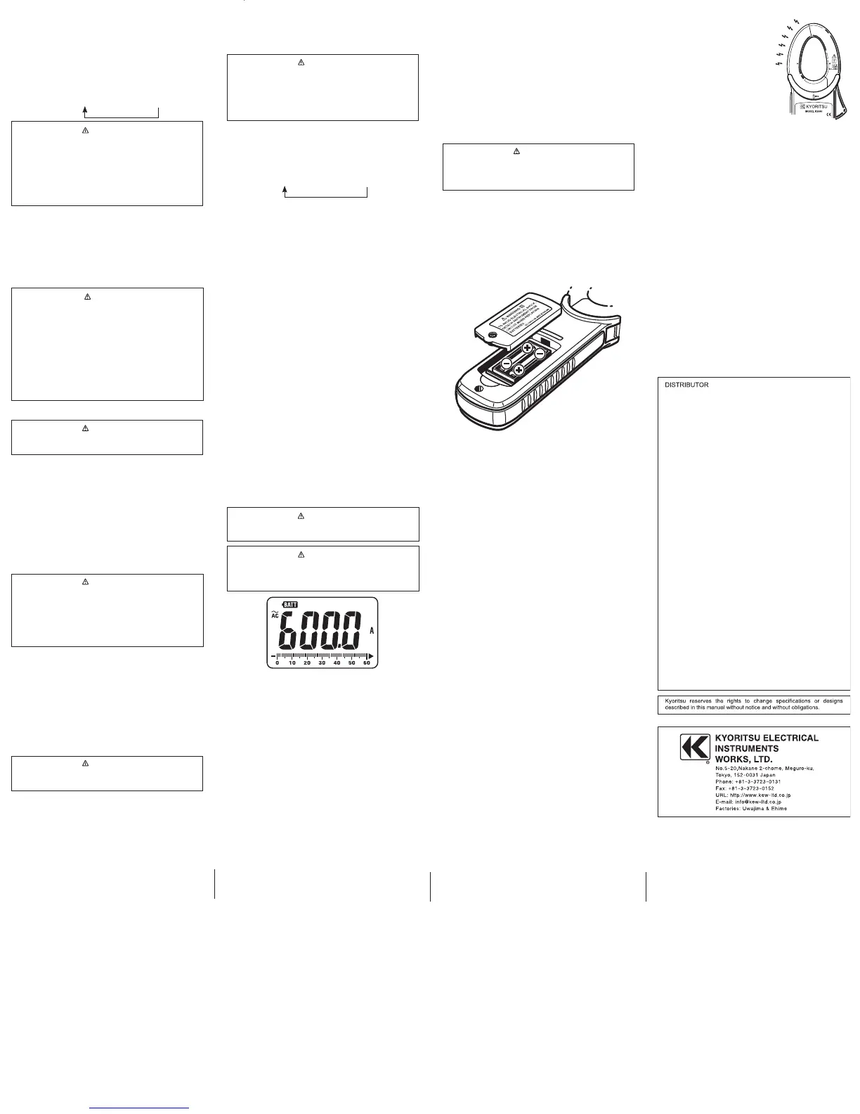
7.BatteryReplacement
WARNING
●
MIN/MAX,PEAKkeysaredisabled whileZERO
Functionisbeingactivated.
CAUTION
●
Donotmixoldandnewbatteries.
●
Installbatteriesincorrectpolarityasindicated
intheBatteryCompartment.
Re place the ba tteries when a Lo w Batt er y
Voltage warning "BATT" mark is indicated on the
display. Note that when the battery is completely
exhausted,thedisplayblankswithout"
BATT
"mark
shown.
(1)SettheFunctionSwitchto"OFF"position.
(2)Unscrew and remove the Battery Compartment
Coveronthebottomoftheinstrument.
(3)Replace the batteries observing correct polarity.
UsenewR03(AAA)orLR03/1.5Vbatteries.
(4)Install the Battery Compartment and tighten the
screws.
display.
(2)With the transformer jaws closed and without
clamping them onto the conductor, press the
"
ZERO
" key to zero adjust the display. (mark is
displayedattheupperrightonthedisplay.)
(3)Pressthetriggertoopenthetransformerjawsand
clampthem ontothe oneconductor undertest, the
conductorshouldbeatthecenterofthejaws,then
takethereadingonthedisplay.
(4)Set theFunctionSwitch toanappropriateposition
accordingtocurrentundertest.
(5)Pressing the "
ZERO
" key again releases "
ZERO
"
function. (mark at the upper right on the display
disappears.)
CAUTION
●
When the current flows from the upside (the
displayside)totheundersideoftheinstrument,
thepolarityofthereadingispositive andvice
versa.
5-3.ACVoltageMeasurement
DANGER
●
Nevermakemeasurementonacircuitinwhich
voltage over AC600V exists to avoid getting
electricalshock.
●
Do not make measurement with the Battery
Coverremoved.
●
Keep your fingers behind the barrier on the
instrumentduringmeasurement.
(1)SettheFunctionSwitchto"
ACV
"position.
(2)ConnecttheredtestleadtoV/
Ω
terminalandthe
blacktestleadtoCOMterminal.
(3)Connect the test leads to the circuit under test.
Take the reading on the display. Pressing the
"
Hz/DUTY
" key while reading is indicated on
the display switches the indication in following
sequence.
ACVoltage⇨Hz⇨DUTY
CAUTION
●
Hz/DUTYFunctionrequiresAC40Vorhigher.
●
To measure a frequency, measure the voltage
ontheelectricalcircuitinadvance.
●
Then press the Hz/DUTY key to enter into
frequencymeasurement.
●
Readings of frequency may fluctuate or be
influencedundernoisyenvironment.
 Loading...