dV-DOSC dV-SUB Manual V3.0 June 2005 6
5. MAINTENANCE AND INSTALLATION TOOLS ...........................................................................137
5.1 Recommended Maintenance Procedures ....................................................................................................137
5.2 Recommend Maintenance Tools.................................................................................................................137
5.3 Spare Parts ................................................................................................................................................137
5.4 Recommended Installation Tools................................................................................................................138
6. SPECIFICATIONS.............................................................................................................................139
6.1 dV-DOSC SPECIFICATIONS .......................................................................................................................139
6.2 dV-SUB SPECIFICATIONS ..........................................................................................................................142
APPENDIX 1: How Does dV-DOSC Behave With Respect To WST Criteria..................................145
APPENDIX 2: How Does the DOSC Waveguide Work? .................................................................. 145
RIGGING CERTIFICATION ........................................................................................................ 147-151
LIST OF FIGURES
Figure 1: Wavefield interference compared to a sculptured dV-DOSC wavefield ..............................................10
Figure 2: Wavefront Sculpture Technology Criteria 1 and 2................................................................................11
Figure 3: Cylindrical versus spherical wave propagation......................................................................................14
Figure 4: Flown and stacked dV-DOSC , dV-SUB configurations ........................................................................15
Figure 5: dV-DOSC 3-way system configuration .................................................................................................18
Figure 6a,b: dV-DOSC 4-way system configuration COMB and cabling options ...........................................19,20
Figure 7: dV-DOSC plus accessories...................................................................................................................21
Figure 8: dV-DOSC rigging accessories................................................................................................................22
Figure 9: dV-DOSC Subwoofer Options..............................................................................................................23
Figure 10: Subwoofer Rigging Accessories...........................................................................................................24
Figure 11: L-ACOUSTICS LA24a, LA48a power amplifiers.................................................................................24
Figure 12: Amplifier Rack Options and Accessories.............................................................................................26
Figure 13: Signal distribution and cabling..............................................................................................................28
Figure 14: Loudspeaker cabling options...............................................................................................................30
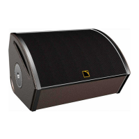
Figure 15: dV-DOSC Enclosure - Front and Rear Views .....................................................................................31
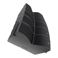
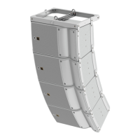
Figure 16: dV-DOSC array...................................................................................................................................31
Figure 17: dV-ANGLE P1 and P2 angle values .....................................................................................................32
Figure 18: dV-BUMP and dV-BUMP2 rigging bumpers .......................................................................................33
Figure 19: dV-DOWN..........................................................................................................................................33
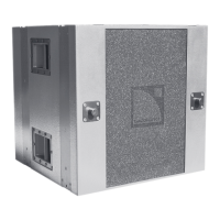
Figure 20: dV-SUB................................................................................................................................................34
Figure 21: dV-ANGLESS sub-to-sub angle bar.....................................................................................................35
Figure 22: dV-ANGLESDP and dVANGLESD angle bars.....................................................................................35
Figure 23: Illustration of dV-SUB rigging configurations.......................................................................................36
Figure 24: dV-DOSC PADO4a Amplifier Rack Panel...........................................................................................39
Figure 25: dV-DOSC PADO2a Amplifier Rack Panel...........................................................................................39
Figure 26: PADO4a amp rack wiring ...................................................................................................................40
Figure 27: PADO2a amp rack wiring ...................................................................................................................41
Figure 28: L-ACOUSTICS AMP RACK RK12-4 ...................................................................................................42
Figure 29: L-ACOUSTICS Amplifier Rack Options..............................................................................................43
Figure 30: L-ACOUSTICS RK122a amplifier rack channel assignments and cabling............................................45
Figure 31: L- L-ACOUSTICS RK124a amplifier rack channel assignments and cabling .......................................45
Figure 32: L-ACOUSTICS RK122a amplifier rack channel assignments and cabling for 2-way stereo presets ...46
Figure 33: L-ACOUSTICS RK122a amplifier rack channel assignments and cabling for 3-way stereo presets ...46
Figure 34: L-ACOUSTICS RK124a amplifier rack channel assignments and cabling for 2-way stereo presets ...47
Figure 35: L-ACOUSTICS RK124a amplifier rack channel assignments and cabling for 3-way stereo presets ...47
Figure 36: CO24 Control Output Panel...............................................................................................................48
Figure 37: MD24 Multi Distro Panel ....................................................................................................................49
Figure 38: CO6 Control Output Panel.................................................................................................................49
Figure 39: dV-DOSC + dV-SUB 3-way stereo preset recommendations..........................................................51
Figure 40: Time alignment guidelines for 3-way SB118 and SB218 presets.........................................................53
Figure 41: Time alignment guidelines for 4-way presets......................................................................................54