Do you have a question about the L3 Aviation Products GH-3100 and is the answer not in the manual?
| Brand | L3 Aviation Products |
|---|---|
| Model | GH-3100 |
| Category | GPS |
| Language | English |
Provides general information about the GH-3100 Electronic Standby Instrument System.
Contains step-by-step procedures for installing the GH-3100 Electronic Standby Instrument System.
Provides procedures for post-installation checks to validate system installation and operation.
Details general flightline maintenance and troubleshooting procedures for the system.
Describes the function descriptions and operation functions for the GH-3100 system.
Introduces the scope and content of Section 1: General Information.
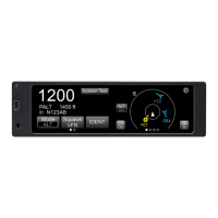
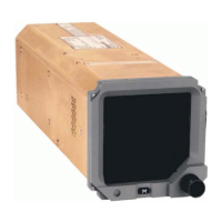
Describes the functional capabilities and components of the GH-3100 system.
Details the technical specifications for the GH-3100 Electronic Standby Indicator.
Lists tools and equipment necessary for installation but not included with the system.
Introduces the installation process for the GH-3100 Electronic Standby Instrument System.
Provides detailed steps for installing the GH-3100 Indicator and associated components.
Details the general requirements for locating and installing the GH-3100 indicator.
Covers the electrical connections and wiring requirements for the GH-3100 system.
Procedures to validate the installation of the GH-3100 system components.
Checks to verify the proper operation of the GH-3100 Electronic Standby Indicator.
Procedures for calibrating and checking the MAG-3000 or MAG-3100 magnetometer.
Information on maintaining the GH-3100 and DCM-3100 for continued airworthiness.
Assists in isolating failures to a defective assembly using symptoms and corrective actions.
Procedures for returning defective GH-3100, DCM-3100, and magnetometers.
Describes the functions and capabilities of the GH-3100 system.
Details the controls on the front panel of the indicator and their functions.
Explains how to navigate and use the menu system for settings and functions.
Describes the sequence of modes the indicator goes through upon power application.
Explains how pitch and roll attitude information is displayed by the indicator.
Details how air data, including altitude and airspeed, is presented on the display.
Describes the display of navigation data from various sources like VOR, ILS, FMS, and TACAN.
Defines digital interface label info and electrical characteristics of GH-3100 signals.
Provides information on the digital interface and bus configurations for the GH-3100.
Details the pin assignments for the J1 connector of the GH-3100 indicator.
Summarizes the environmental qualifications and test results for the GH-3100 and DCM-3100.