Do you have a question about the L3 Communications ProTec AISD1000-00 and is the answer not in the manual?
Overview of the L-3 ProTec AIS transponder, its compliance, and automated system features.
Details on standards, reporting capacity, transmitter, receiver, and DSC receiver specifications.
Describes the unit's compact design, integral MKD, GPS, and data interface features.
Details pilot system input/output, long range equipment interface, and data formats.
Explains GPS and sensor input sentences, including DTM, GGA, GLL, etc., and their data fields.
General overview of the unit's operation and user interface.
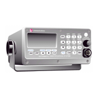
Details the MKD, its functions, and controls like Power/Dim, LCD, and Keypad.
Explains the function of various keys on the keypad, including navigation and special function keys.
Describes the NAV display screen and Own Ship Information display screens.
Covers menu navigation, logon, system info, vessel/voyage setup, channels, antenna position, and password management.
Details how to view safety text, alarms, general status, and down-time logs.
Overview of the installation process, including transponder, antennas, and data interface.
Details on mounting the transponder unit, terminal block, and power connections.
Explains connecting data channels, cables, and terminal blocks for sensor input.
Guidelines for installing the VHF antenna, including placement and cable connections.
Instructions for installing the GPS antenna, focusing on placement and signal reception.
Steps for powering up the unit and performing initial vessel/voyage setup and antenna configuration.
Provides overall dimensions and mounting details for the AIS transponder.
Presents overall dimensions of the AIS transponder unit.
Illustrates the wiring connections for the IEC data cable and its components.
Checklist for physical installation of transponder, cables, and antennas.
Checklist for initial power-up, data entry, and system configuration.
Checklist for verifying antenna setup, GPS linkup, and absence of alarms.
| Brand | L3 Communications |
|---|---|
| Model | ProTec AISD1000-00 |
| Category | Marine Radio |
| Language | English |