28
INSTALLATION: (Con’t)
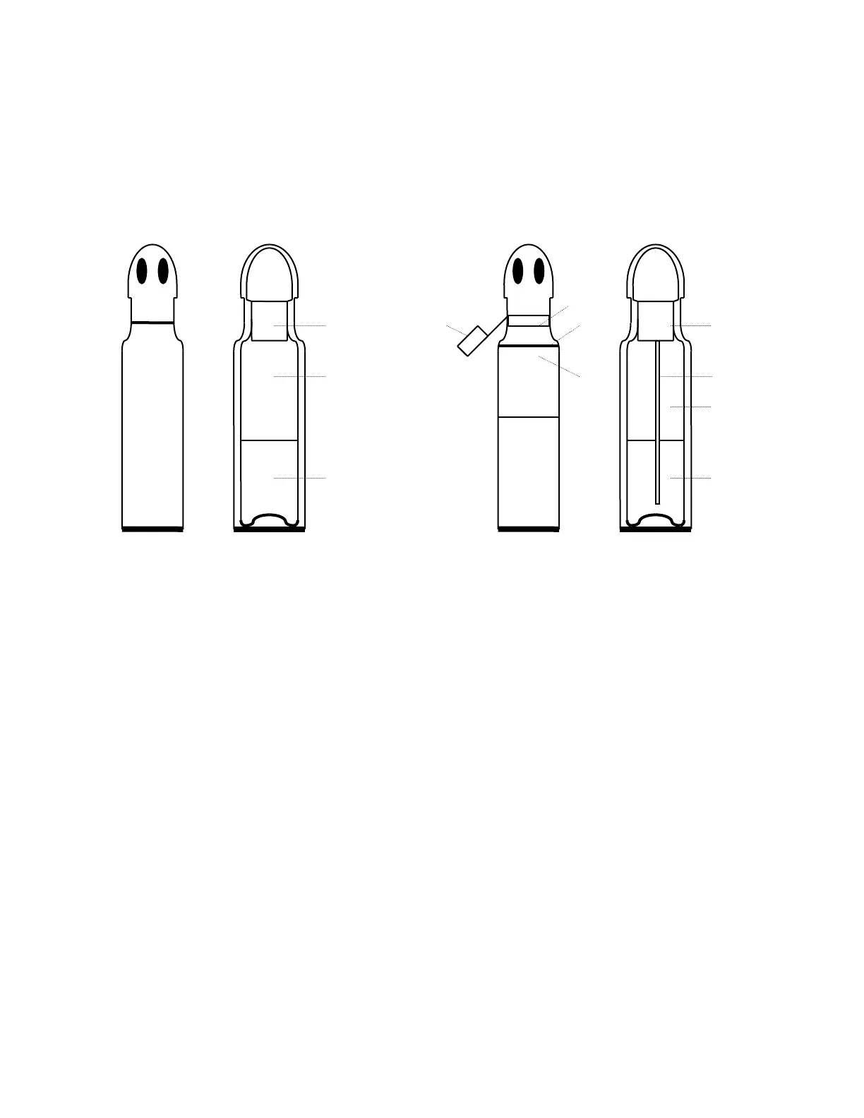
STANDARD AND SIPHON TYPE CO2 GAS CYLINDERS
STANDARD TYPE (CORRECT) SIPHON TYPE (INCORRECT)
2
1 1 3 5
2 4 6
7
3 8
1. Compressed Gas Association 1. Warning tag indicating that
#320 connector. cylinder is siphoning type.
2. Gas head space. 2* Aluminum ring.
3. Liquid CO2 filled to 68% 3* Gold band.
equal weight of water that 4* Stamp or marking on cylinder:
cylinder would hold at 60ºF. "Siphon" or "Eductor Tube".
5* Valve should be of special type for
service.
6* Withdrawal tube draws up the liquid
CO
2.
7* Gas head-space.
8* Liquid CO2 filled to 68% equal weight of
water that cylinder will hold at 60ºF.
*NOTE: SOME GAS SUPPLIERS WILL HAVE NO MARKINGS TO INDICATE AN "EDUCTOR
TUBE" OR "SIPHON" TYPE CYLINDER—BE SURE TO ORDER DRY, LAB-GRADE CO2.
Be sure to obtain a dual-stage regulator from the gas supplier for the CO2
tank that is to be installed according to local codes. Connect ¼" ID (6.35 mm)
flexible tubing to the regulator. Connect the other end of the tubing to the unit's
CO2 inlet (located on the back top panel). Insert tubing over hose barb and
fasten with an appropriate clamp to assure a proper connection. Adjust the
regulator for 5 psi when CO
2 is to be injected into chamber. For optimum results,
do not exceed or reduce this pressure.
 Loading...