EasyManua.ls Logo

Lafayette HE-30 - Page 4

Default Icon
21 pages
Print Icon
To Next Page IconTo Next Page
To Previous Page IconTo Previous Page
Loading...
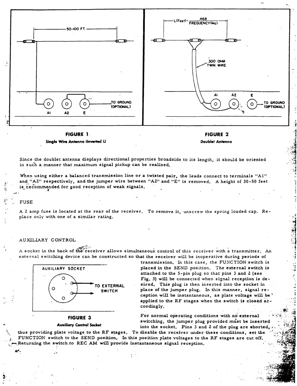
468
L(Feet]=
=e
GueNcy
(Me)
300
OHM
TWIN.
WIRE
Al
A2
E
©)
Ce
TO
GROUND.
©
(3)
-
(To
GROUND
(OPTIONAL)
cae
(OPTIONAL)
%
st
ae
FIGURE
1.
FIGURE
2
4
Single
Wire
Antenna
{inverted
LU)
Doublet
Antenna
3
Since
the
doublet
antenna
displays
directional
properties
broadside
to
its
length,
it
should
be
oriented
“al
in
such
a
manner
that
maximum
signal
pickup
can
be
realized,
oe
“nd
When
using
either
a
balanced
transmission
line
or
a
twisted
pair,
the
leads
connect
to
terminals
"Al"
ee
S
and
''A2"
respectively,
and
the
jumper
wire
between
"A2"
and
"E"
is
removed.
A
height
of
30-50
feet
r
e
is”
recommended
for
good
reception
of
weak
signals,
—
t
"|
FUSE
.
A
2
amp
fuse
is
located
at
the
rear
of
the
receiver.
To
remove
it,
unscrew
the
spring
loaded
cap.
Re-
place
only
with
one
of
a
similar
rating.
AUXILIARY
CONTROL
‘
A
socket
in
the
back
of
the’
receiver
allows
simultaneous
control
of
this
receiver
with
a
transmitter.
An
external
switching
device
can
be
constructed
so
that
the
receiver
will
be
inoperative
during
periods
of
mee
transmission,
In
this
case,
the
FUNCTION
switch
is
AUXILIARY
SOCKET
placed
in
the
SEND
position.
The
external
switch
is
attached
to
the
5-pin
plug
so
that
pins
3
and
2
(see
Fig.
3)
will
be
connected
when
signal
reception:is
de-
G
TO
EXTERNAL
.
sired.
This.
plug
is
then
inserted
into
the
socket
in
SWITCH
place
of
the
jurnper
plug.
In
this
manner,
signal
re-
ception
will
be
instantaneous,
as
plate
voltage
will
be.‘
applied
to
the
RF
stages
wher
the
switch
is
closed
ac-
Concetehy:
‘howe
t
pe
Lisi
Zh
hehe
ass
FIGURE
3
For
normal
operating
conditions
with
no
external
-
>>
-
switching,
the
jumper
plug
provided
must
be
inserted
if
Auxiliary
Control
Socket
into
the
socket,
Pins
3
and
2
of
the
plug
are
shorted,
:.
~
x
thus
providing
plate
voltage
to
the
RF
stages,
To
disable
the
receiver
under
these
conditions,
set
the
~”:
,
"4
FUNCTION
switch
to
the
SEND
position,
In
this
position
plate
voltages
to
the
RF
stages
are
cut
off,
a=
Returning
the
switch.to
REC
AM
will
provide
instantaneous
signal
reception,
:
et
e

Other manuals for Lafayette HE-30

Related product manuals