ENG ENG
Terminals
The terminals on PCB can be used to connect the power supply and the controlled device.
Terminal Function
COM Common
NO Normal Open
NC Normal Close
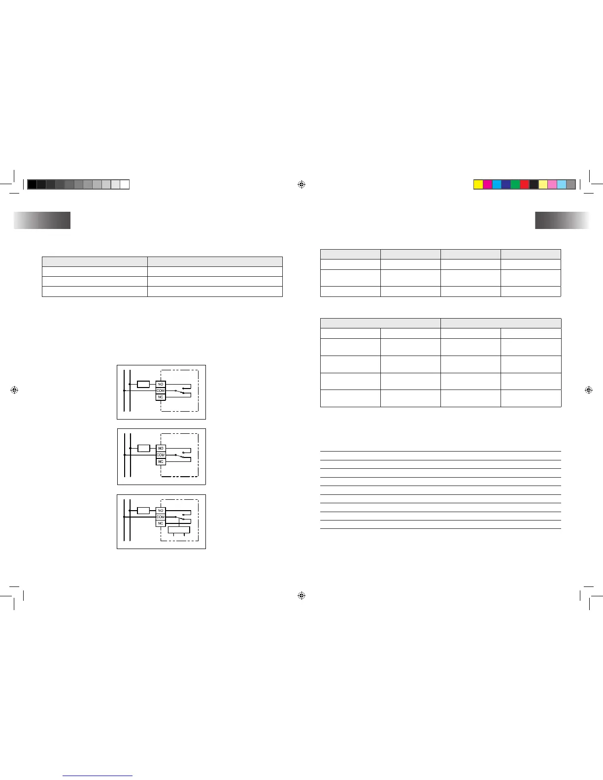
Wiring diagram
Connect the system wires to the terminals according to below wiring diagram.
Connect 230VAC live to terminal “COM”.
Connect heater/Cool in series with terminal “NO ” and 230VAC Neutral.
Closed the housing.
1�
2�
3�
Switches
The switches on PCB can be used to turn on or off of below functions.
Switch Function OFF On
Heat/ Cool Heat /cool system Heat (Default) Cool
PWM Control mode
On-off Control
(Default)
PWM Control
C/F Temperature Scale Celsius (Default) Fahrenheit
The switches SPAN1 and SPAN2 on PCB use to select the SPAN as per below table.
Switch Control mode
SPAN2 SPAN1 On-Off Control PWM Control
Off (Default) Off (Default) 0,5°C/ 1°F
1,0°C/ 2°F,
300 secondi
Off On 1,0°C/ 2°F
2,0°C/ 4°F,
300 secondi
On Off 1,5°C/ 3°F
1,0°C/ 2°F, 300
secondi
On On 2,0°C/ 4°F
2,0°C/ 4°F,
300 secondi
The factory default setting for all these functions are listed on above table
Dati tecnici
Dimensions: 106 (L) x 106 (A) x 31 (P) mm
Materials: Polycarbonate (PC)
Weight: 200 g
Battery: Alkaline AA 1,5 V x 2
Max. Switching voltage: ~ 230 V CA/ 50 Hz
Max. Switching current: ~ 3(1) A
Temperature control range: 10 - 35°C
Temperature Control Span: 0,5/1/1,5/2°C
Operating temperature: 0°C - 50°C
Storage temperature: -20°C - 60°C