1. Reference
7
1. Reference
CO2 Laser Machine © 2018 Laguna Tools 8/27/2018
EN
1.2 Dimensions
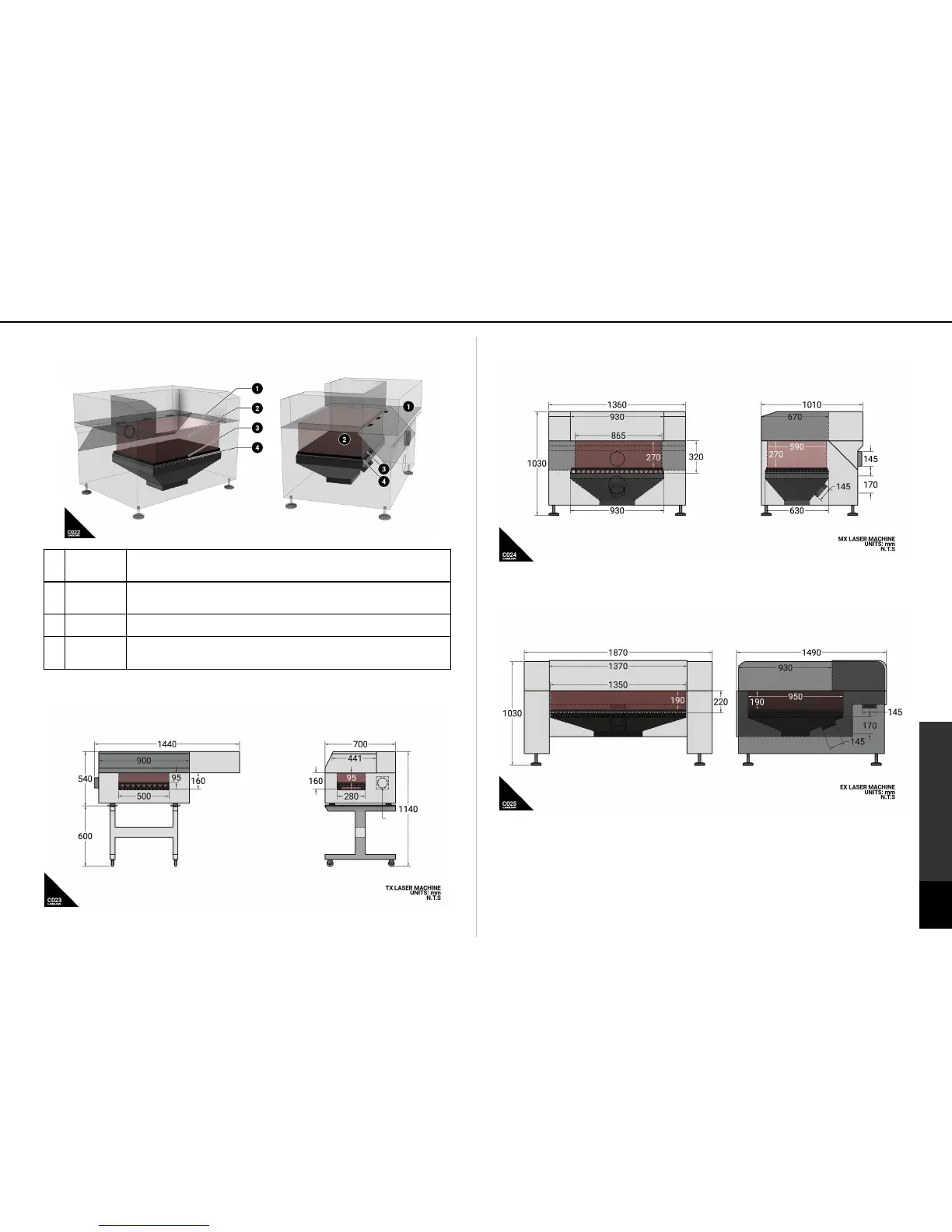
Fig C022: Laser machine capacities and effective volume.
This is the relative plane that the drive system is mounted to. It serves as a "reference"
plane to the z axis range of the laser- "able" volume. The laser head assembly has a small
range of adjust-ability that will allow it to go a 1-3" from this plane in the z direction.
This is the area that can be processed by the drive system. The edges are defined by the
X,Y, and Z limits of the laser machine (see below). Both (2) Honeycomb Table and (3)
Material Ribs can be removed for additional Z-axis range.
The honeycomb table is ideal because it is not damaged ruined by the laser beam and will
remain flat. This table can be removed to allow for additional Z-axis range.
The metal ribs are used as effectively as the honeycomb table for larger materials. Like
the honeycomb table, the laser does not harm the build materials and ribs will remain flat.
The ribs can also be removed and replaced.
TX (SKU1)
Fig C023: TX Laser machine capacities and dimensional drawing.
MX (SKU3)
Fig C024: MX Laser machine capacities and dimensional drawing.
EX (SKU3)
Fig C025: EX Laser machine capacities and dimensional drawing.