▪ USB Connector: The development kit provides a USB Type Micro-B connector (USB1) which allows connection to any
USB host device. The connector optionally supplies power to the development kit and the USB signals are connected
to a USB-to-serial converter device (FT232R) when SW4 is set to the USB position.
▪ USB – UART: The development kit is fitted with a (U10) FTDI FT232R USB-to-UART converter which provides USB-to-
Virtual COM port on any Windows PC (XP or later). Upon connection, Windows auto-installs the required drivers. For
more details and driver downloads, visit the following website: http://www.ftdichip.com/Products/FT232R.htm.
▪ UART Interface Driven by USB FTDI Chip: In normal operation, the BL654 UART interface is driven by the FTDI FT232R
USB-to-UART converter.
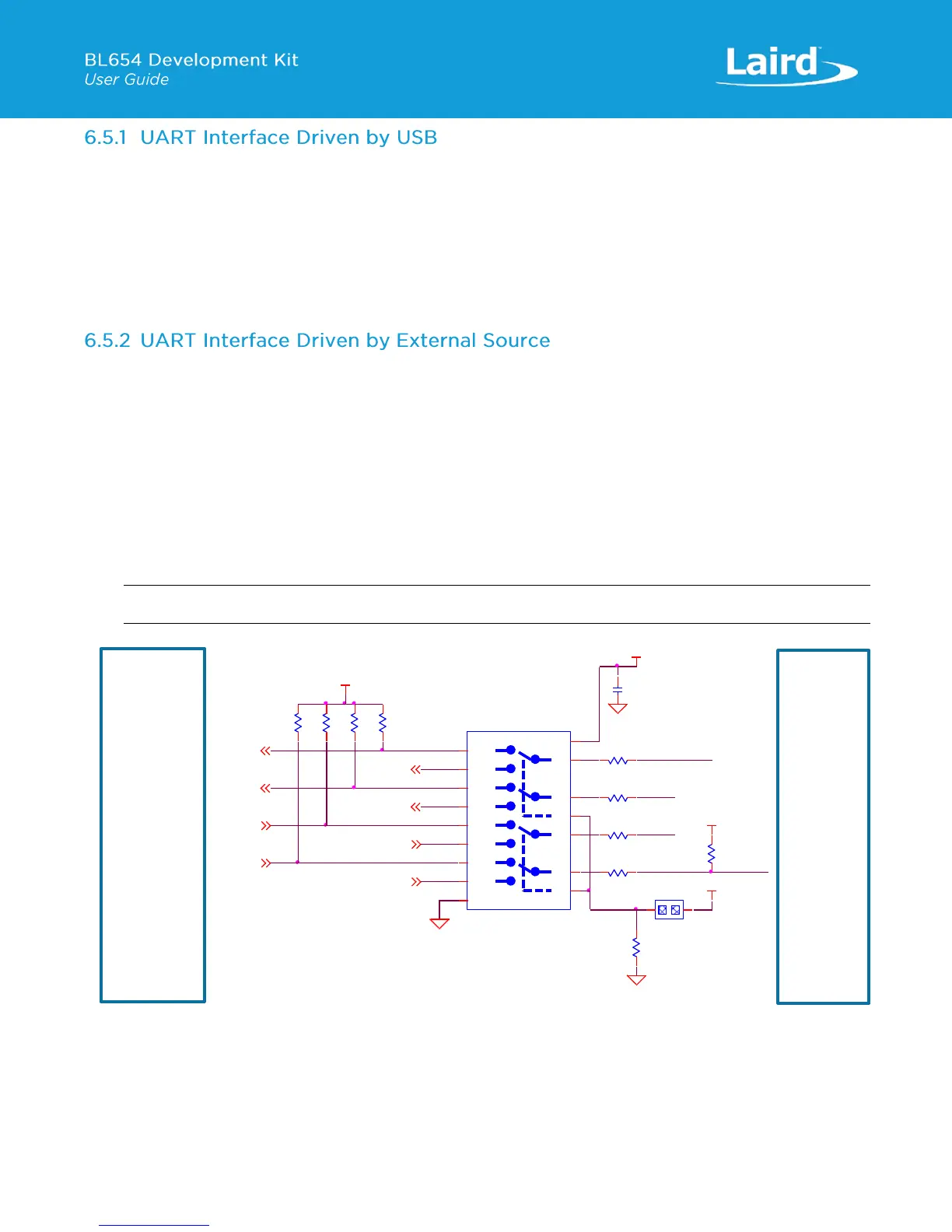
▪ UART Interface Driven by External UART Source: The BL654 module UART interface (TX, RX, CTS, RTS) is presented at
a 2.54 mm (0.1”) pitch header (J1). To allow the BL654 UART interface to be driven from the breakout header
connector (J1), the following must be configured:
– The development board must be powered from a DC jack (CON1) or AAA batteries (J25) and with switch SW4 in
DC position.
– The FTDI device must be held in reset. This is achieved automatically by removal of the USB cable (from
connector USB1), placing SW4 in the DC position or fitting a jumper on J27.
– Fit a jumper on J35 (to switch the Analog switch U15 and route BL654 UART to J1) when connecting an external
UART source (for example FTDI USB-UART TTL (3.3V) converter cable) using J1. This isolates the BL654 UART
from the on-board USB-UART FTDI device. By default, the jumper on J35 is not fitted, so by default BL654 UART
is routed to U10 FTDI FT232R USB –UART converter.
Note: The BL654 UART signal levels always need to match the supply voltage net VDD_VSRC_nRF, of the BL654.
Figure 10: USB to UART (via FTDI chip on devboard) interface via analog switch U15
J1 pinout is designed to be used with FTDI USB-UART TTL (3.3V) converter cables (found at
http://www.ftdichip.com/Products/Cables/USBTTLSerial.htm). One example is FTDI part TTL-232R-3V3.
 Loading...
