Tying nAutoRUN HIGH (to net name on devboard VDD_VSRC_nRF) inhibits the $autorun$ application from running. As an
alternative to using USB_DTR, the J12 three-pin header allows a jumper to be fitted to select between the two operating
modes.
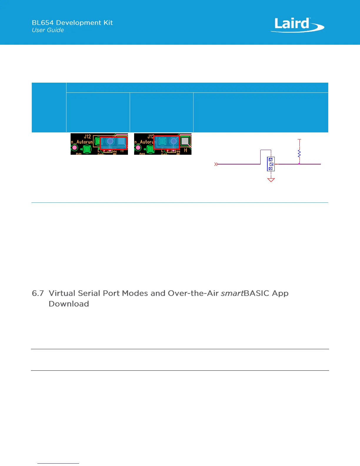
Table 5: BL654 nAutoRUN header
The J12 header connector allows the USB_DTR signal from the FTDI chip to be disconnected from the BL654.
To connect the BL654 nAutoRUN pin SIO_35 (pin 5) to PC FTDI USB_DTR line via the J12 header connector, do the following:
▪ Fit the jumper into the J12 (pin 2-1) header connector to allow the PC (using UwTerminal) to control nAutoRUN pin
(SIO_35).
To disconnect the BL654 nAutoRUN SIO_35 (pin 5) from the PC FTDI USB_DTR line, do the following:
▪ Remove the jumper on header connector J12 pin 2-1. Then nAutoRUN can be controlled by inserting the jumper onto
J12 (pin 2-3) as shown in Table 5 (this is the default). The BL654 by default has pull-down enabled on the SIO_35
(nAutoRUN) pin, so the jumper into J12 (pin 2-3) is optional.
The Over-the-Air (OTA) feature makes it possible to download smart BASIC applications over the air to the BL654. To enable
this feature, SIO_02 must be pulled high externally.
On the development board, header connector J5-pin1 brings out the BL654 SIO_02; J5-pin 2 brings out VCC_nRF_SW. To
pull BL654 SIO_02 high (to net name VCC_nRF_SW on devboard), fit jumper into header J5.
Note: When SIO_02 is high, ensure that SIO_35 (nAutoRun) is NOT high at same time, otherwise you cannot load the
smartBASIC application script.
This section discusses Virtual Serial Port (VSP) Command mode through pulling SIO_02 high and nAutoRUN (SIO_35) low.
Refer to the documentation tab of the BL654 product page:
http://www.lairdtech.com/products/bl654-ble-thread-nfc-modules.
Figure 13 shows the difference between VSP Bridge to UART mode and VSP Command mode and how SIO_02 and
nAutoRUN (SIO_35) must be configured to select between these two modes.

 Loading...