The I2C RTC chip (U16) allows the BL654 I2C interface to be tested. The output of the RTC chip (U16) is on the I2C bus and is
by default connected to the BL654 module via jumpers on J17 and J21.
Table 11: I2C RTC chip BL654 I2C signal mappings
Fitting a jumper on J17 routes the RTC_SCL signal to BL654 SIO_27 and fitting a jumper on J21 routes the RTC_SDA to BL654
SIO_26.
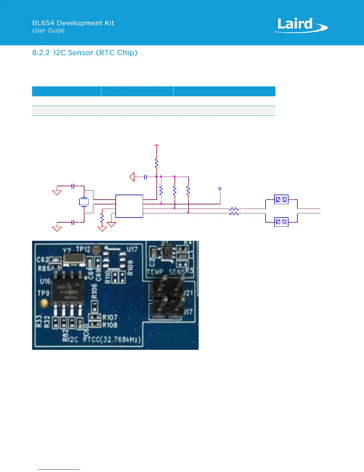
Figure 15: I2C device RTC chip schematic and PCB
To test the BL654 I2C interface, use smartBASIC application rtcs.erver.sb in the GitHub smartBASIC sample application
repository on the BL654 product page at https://github.com/LairdCP/BL654-Applications. This application runs on the
BL654 and can be used with an Android phone (requires an app such as nRF connect,
https://play.google.com/store/apps/details?id=no.nordicsemi.android.mcp&hl=en_GB) or another
BT900/BL620/BL652/BL654 loaded with “rtcc.lient.sb”.
The smartBASIC application “rtcs.erver.sb” is a BLE RTC server, and it advertises the current time (which it gets from the I2C
RTC chip (U4)).
 Loading...
