www.lairdtech.com/bluetooth
30
© Copyright 2018 Laird. All Rights Reserved
Americas: +1-800-492-2320
Europe: +44-1628-858-940
Hong Kong: +852 2923 0610
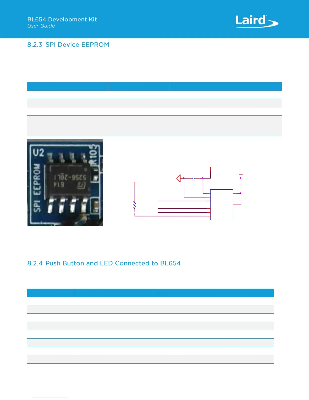
The SPI EEPROM device (U2) is connected to the BL654 SPI pins directly. By default, the BL654 Module SIO_44 (used as the
SPI_CS) is connected to EEPROM (U2) slave select line. Table 12 lists signal mappings of how the SPI EEPROM (U2) is wired
to BL654 SIO pins.
Table 12: SPI EEPROM to BL654 SPI signal mappings
(U2pin6) Eeprom_SCK_SIO_41
(U2pin2) Eeprom_MISO_SIO_04
(U2pin5) Eeprom_MOSI_SIO_40
(U2pin1) Eeprom_CS_SIO_44
Configure SIO_44 as an output and drive output
low in smartBASIC application to select SPI slave
(SPI EEPROM U2).
Figure 16: SPI EEPROM schematic and PCB
For a working example of the BL654 SPI interface using the SPI EEPROM (U2), a smartBASIC application for this will be
available in the future in the GitHub smartBASIC sample application repository on the BL654 product page at
https://github.com/LairdCP/BL654-Applications.
The two push buttons and two LEDs on the BL654 are connected to dedicated SIOs of the BL654 module.
Table 13: LED’s and Buttons to BL654 SIO signal mappings
Pin 20 SIO_13 (via header J26)
To connect LED1 to SIO_13, fit jumper in J26
Pin 22 SIO_14 (via header J37)
To connect LED1 to SIO_14, fit jumper in J37
Pin 18 SIO_15 (via header J26)
To connect LED1 to SIO_15, fit jumper in J45
Pin 21 SIO_16 (via header J37)
To connect LED1 to SIO_16, fit jumper in J39
VDD_VSRC_nRF
R105
10K
U2
256Kb,20MHz
CSn
1
SO
2
WPn
3
GND
4
SI
5
SCK
6
HOLDn
7
VCC
8
Eeprom_CS_SIO_44
C1
0.1uF,16V
VDD_VSRC_nRF
Eeprom_MOSI_SIO_40
Eeprom_SCK_SIO_41
Eeprom_MISO_SIO_04
VDD_VSRC_nRF
GND
SPI sensor (Eeprom 256kb)
VDD 1.7V-5.5V
 Loading...
