www.lairdtech.com/bluetooth
31
© Copyright 2018 Laird. All Rights Reserved
Americas: +1-800-492-2320
Europe: +44-1628-858-940
Hong Kong: +852 2923 0610
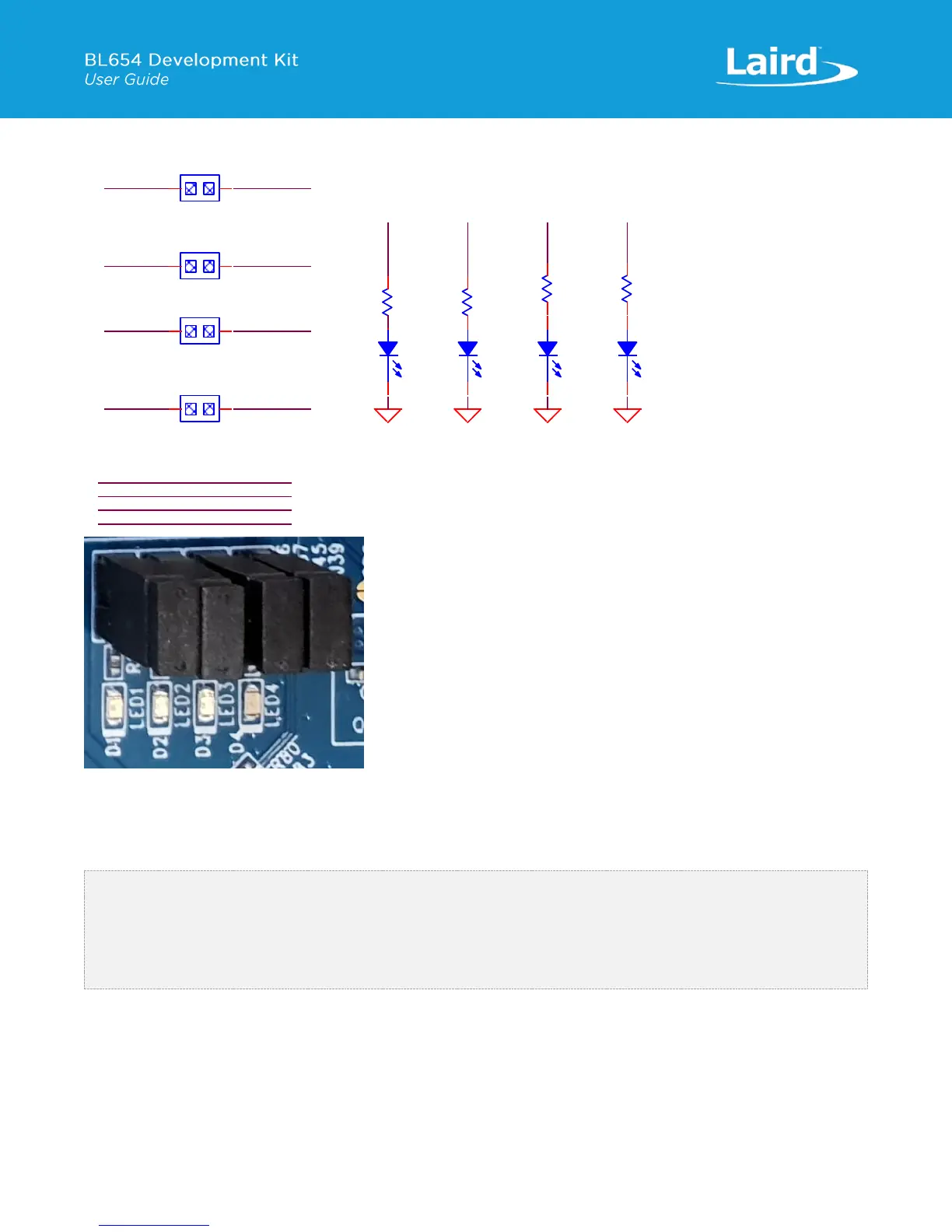
Figure 17: LEDs and Buttons schematic and PCB
The buttons (BUTTON1 and BUTTON2 for example) have no external pull-up resistor, so to use the buttons, the SIO_11 and
SIO_12 pins must be configured as inputs with internal pull-up resistors (which is the default). The following smartBASIC
lines configure the pull-ups:
rc = GPIOSETFUNC(11,1,4) '//sets SIO_11 (Button1) as a digital in,
strong pull up
rc = GPIOSETFUNC(12,1,4) '//sets SIO_12 (Button2) as a digital in,
strong pull up
Refer to the smartBASIC application script example “btn.button.led.test.sb” in the GitHub smartBASIC sample application
repository on the BL654 product page at https://github.com/LairdCP/BL654-Applications
The LEDs are active high, meaning that writing a logical one (“1”) to the output pin illuminates the LED.
One example of when push buttons can be used is when a smartBASIC application is written to simulate a generic data
profile. Push buttons can then be pressed to increment and decrement, such as a heart rate.
SIO_15
SIO_14
SIO_13
SIO_16
PIN HEADER,2.54mm 1X2P
J37
1
1
2
2
LED2
LED4
PIN HEADER,2.54mm 1X2P
J39
1
1
2
2
PIN HEADER,2.54mm 1X2P
J45
1
1
2
2
LED3
LED1
PIN HEADER,2.54mm 1X2P
J26
1
1
2
2
LED3
GND
LED3
R29
1K
D3
Blue,0603
1
2
LED4
GND
LED4
D4
Blue,0603
1
2
R31
1K
GND
LED1
R15
1K
LED1
D1
Blue,0603
1
2
GND
LED2
R16
1K
LED2
D2
Blue,0603
1
2
BUTTON4SIO_25
BUTTON3SIO_24
SIO_11 BUTTON1
SIO_12 BUTTON2
 Loading...
