There are two primary ways to measure the current consumption:
▪ Using Ammeter – Cut solder bridge SB1 and connect an ampere meter between the two pins of J7 pins 1-2. This
monitors the current directly. This is when BL654 is powered using the normal voltage Mode (BL654 operated VDD
pin). If the BL654 is powered using the high voltage Mode (BL654 operated VDD_HV pin), then only cut solder bridge
SB13 and connect an ampere meter between the two pins of J9 (pins 1-2).
▪ Using Oscilloscope – The open solder bridge SB2 first needs to be shorted with solder, then the on-board 10 Ohm
resistor R76 which is mounted across J7 pins 1-2 can be used as current sense resistor. Connect an oscilloscope or
similar with two probes on the pins on the J7 connector and measure the differential voltage drop. The voltage drop is
proportional with current consumption. If the 10 Ohm resistor is chosen, 10 mV equals 1mA.
This method allows the dynamic current consumption waveforms to be shown on an oscilloscope as the BL654 radio
operates. This can provide insight into power optimization.
▪ Power Profiler Kit (PPK) from Nordic – For more details, refer to http://www.nordicsemi.com/eng/Products/Power-
Profiler-Kit/(language)/eng-GB
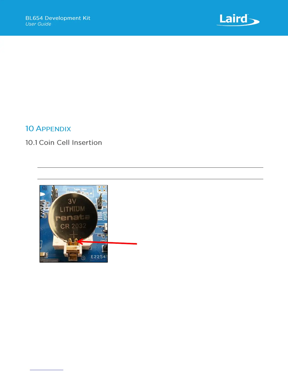
To insert the coin cell, follow these steps:
1. Push the coin cell against positive contact spring of holder J34 (on the back side of the dev board).
Note: The coin cell sits below the positive contact spring (as shown with arrow).
Figure 22: Inserting the coin cell (step 1)
3. Push the coin cell down into the holder (J34).
 Loading...
