Do you have a question about the Lake Shore 218S and is the answer not in the manual?
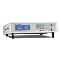
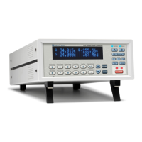
Provides an overview of the Model 218 temperature monitor and its.
Details the key features of the Model 218, including sensor measurement.
Lists the technical specifications for the Model 218, covering hardware and.
Covers essential safety precautions for operating and handling the Model 218.
Introduces the importance of selecting the proper sensor for temperature monitoring.
Discusses factors for choosing temperature sensors, including range and.
Explains options for calibrated sensors and their benefits for accuracy.
Provides detailed instructions on sensor installation, covering materials and.
Provides general information and procedures for installing the Model 218.
Instructions for inspecting the instrument upon receipt and unpacking.
Procedure for safely repackaging the instrument for return or.
Details the connectors and assemblies found on the rear panel of the.
Covers sensor input connectors, pinouts, and wiring for the Model 218.
Describes the terminal block connections for relays and analog outputs on.
Introduces the chapter covering the Model 218 front panel operations.
Explains the layout and functions of the Model 218's LCD display.
Details the functions of each key on the Model 218's front panel keypad.
Describes how to select the sensor type for input groups on the Model.
Explains how to assign a temperature response curve to a sensor input.
Covers math features like Max/Min, Linear equation, and filtering.
Details the configuration and operation of analog voltage outputs on.
Explains how to set up and operate high and low alarms for each input.
Describes how to reset latched alarms on the Model 218.
Details how to configure relays for alarm or manual control on the Model.
Explains how to use the keypad lock feature to prevent accidental changes.
Procedure for resetting all Model 218 parameters to factory defaults.
Introduces special features not used during normal operation.
Instructions for entering and managing custom temperature response curves.
Details the SoftCal™ algorithms for inexpensive sensor calibrations.
Information on using the Model 218's internal memory for data logging.
Describes how to connect a printer and print data from the Model 218.
Introduces operational instructions for the computer interfaces.
Details the IEEE-488 interface capabilities and setup.
Describes the serial interface, its features, and connection requirements.
Provides guidance for troubleshooting common communication issues.
Lists and describes commands for controlling the instrument remotely.
Commands for configuring and querying input alarm parameters.
Commands for configuring and querying analog output parameters.
Command to generate a SoftCal™ curve from calibration data.
Queries sensor units reading for single or all inputs.
Provides general service information and contact details for issues.
General safety precautions to observe during maintenance procedures.
Information on preventing damage from electrostatic discharge (ESD).
Describes the fuse drawer and its role in line voltage selection.
Procedure for changing the instrument's line voltage selector.
Instructions for safely replacing line fuses in the instrument.
Details the pinout for the sensor input connectors on the rear panel.
Describes the IEEE-488 interface connector and its wiring.
Provides information on serial interface cables and adapters.
Instructions for removing and replacing the top enclosure.
Procedure for replacing the EPROM and NOVRAM ICs.
Lists and explains error messages that may appear during operation.
Detailed steps for calibrating sensor inputs and analog outputs.
Lists interface commands used for calibration procedures.
Introduces information on models, options, and accessories.
Lists the available Model 218 model numbers and their descriptions.
Lists available options for the Model 218, such as CalCurve™.
Lists accessories available for the Model 218.
Details the types of cryogenic wire sold by Lake Shore.
Describes Apiezon® “N” Grease for cryogenic applications.
Describes Indium Foil used for sealing in cryogenic applications.
Instructions for adding ferrite noise filters to sensor cables.
Details the kit for mounting a half-rack unit in a 19-inch rack.
Details the kit for mounting two half-rack units in a 19-inch rack.
Provides curve tables applicable to the Model 218 Temperature Monitor.
Introduces the appendix containing curve tables for the Model 218.
Table of breakpoints and temperature values for the DT-470 diode.
Curve tables for other standard diode and platinum sensors.
Table of breakpoints and temperature values for the DT-670 diode.
| Control Outputs (Heater) | 1 |
|---|---|
| Control Outputs (Analog) | 1 |
| Input Channels | 8 |
| Sensor Input Type | Diode, RTD, Thermocouple |
| Computer Interface | IEEE-488, RS-232 |
| Temperature Stability | 0.01 K |
| Sensor Types | Diode, RTD, Thermocouple |
| Control Outputs | 1 Heater, 2 Analog |
| Output Type | Analog, Heater |
| Communication Interface | IEEE-488, RS-232 |
| Power Supply | 100 to 240 VAC, 50/60 Hz |
| Dimensions | 89 mm |