Do you have a question about the Lake Shore 420 and is the answer not in the manual?
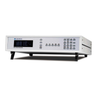
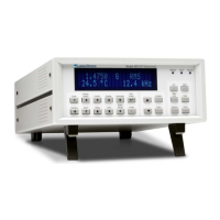
Overview of the Model 420 Gaussmeter and its design.
Details the front panel, display, measurement capabilities, and functions.
Explains the risk of ESD to electronic components.
Outlines general safety precautions for instrument operation and service.
Defines various safety symbols used in the manual.
Shows industry symbols for ESDS components.
Provides precautions for handling ESDS components safely.
Introduces the chapter on installation procedures.
Guides on checking for damage and verifying shipment contents.
Instructions for returning the instrument for service or repair.
Describes the purpose of each connector on the rear panel.
Step-by-step guide to verify basic unit operation before use.
Introduces the chapter on operating the Gaussmeter.
Explains the function of each key on the front panel.
Describes how to capture and reset the maximum field reading.
Details the procedure for nulling ambient fields from the probe.
Explains how to manually select or automatically set measurement ranges.
Describes how to switch between AC and DC measurement modes.
How to toggle between Gauss and Tesla units for display.
How to set the baud rate for serial communication.
Explains how to set a relative setpoint for measuring small field variations.
Describes the corrected and monitor analog outputs.
Procedure to prevent unauthorized changes to settings.
How to reset the instrument to its default configuration.
General guidance for probe care, usage, and accuracy.
Procedure for safely replacing the probe.
Instructions for handling fragile probes to avoid damage.
Guidance on orienting probes for accurate measurements.
Factors affecting measurement accuracy, including angle and temperature.
Introduces the chapter on remote operation via serial interface.
Covers hardware configuration and connection for RS-232C communication.
Technical description of serial interface specifications.
How to configure baud rate and other serial parameters.
Example code for computer control.
Tips and conventions for serial commands.
Lists available commands for remote control.
Explains the syntax for commands and queries.
Details commands for general instrument settings.
Lists commands specific to the Gaussmeter's functions.
Introduces the chapter on service and maintenance.
Provides solutions for common operational issues.
Guide for adjusting voltage settings and replacing fuses.
Detailed pinouts and descriptions for rear panel connectors.
Wiring information for connection cables and adapters.
Steps to replace the instrument's firmware chip.
Introduces the chapter on accessories and probes.
Lists optional devices that enhance the primary unit.
Details available probes, their types, and selection criteria.
Introduces the appendix on Hall Generators.
Explains the fundamental principles of the Hall effect.
Describes the physical dimensions of the Hall sensor's active region.
Explains axial vs. transverse probe configurations.
Crucial instructions for safely handling fragile Hall generators.
How current and field direction affect output voltage polarity.
Describes the wiring color codes for Hall generator leads.
Basic connection diagram for Hall generators.
Specifics on connecting Hall generators to the Gaussmeter.
Technical data for various Hall generator models.
Software utility for calibrating Hall probes.
| Brand | Lake Shore |
|---|---|
| Model | 420 |
| Category | Measuring Instruments |
| Language | English |