Do you have a question about the Lake Shore Model 421 and is the answer not in the manual?
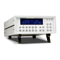
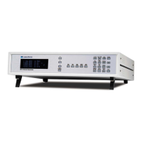
Provides a general overview of the Model 421 Gaussmeter and its key features.
Details the Model 421's design, performance capabilities, and suitability for magnetic measurements.
Presents detailed technical specifications including measurement ranges, resolution, and interface capabilities.
Outlines essential general safety precautions to observe during operation, service, and repair.
Explains the meaning of various safety symbols used in the manual for hazard identification.
Provides general instructions and guidelines for installing the Model 421 Gaussmeter.
Instructions for checking the received system for damage and verifying all components are present.
Guidance on how to properly package the instrument for return or shipping, including RGA number.
Identifies and explains the purpose of each connector on the rear panel of the Model 421.
Details the power input, voltage selection, fuse verification, and power switch for the instrument.
Instructions on connecting a Hall effect probe to the gaussmeter, including safety precautions.
Describes the corrected and monitor analog output signals available from the instrument.
Information on the relay terminal block used for alarm output connections and its configuration.
Procedure to verify basic operation of the gaussmeter after installation, including probe zeroing.
Provides an overview of the Model 421's operation, including front panel controls and functions.
Defines the functions of the keys and display elements on the front panel of the Model 421.
Explains how to switch between Gauss (G) and Tesla (T) units for magnetic field display.
Details how to select between AC and DC magnetic field measurement modes and use the display filter.
Describes the function of the display filter for improving readability in noisy fields.
Covers manual and auto-range settings for optimizing measurement precision across different probes.
Procedure to null the probe offset for accurate DC field measurements, often using a zero gauss chamber.
Explains how to capture and reset the maximum magnetic field reading displayed by the instrument.
Describes how to set a relative setpoint and view field deviations from that setpoint.
Details how to configure alarm setpoints, audible alerts, and relay outputs for testing and sorting.
Describes the corrected and monitor analog output signals and their scaling.
Covers configuration of the serial interface, primarily setting the baud rate for communication.
Explains how to enable faster data transfer rates via the serial interface for increased throughput.
Procedure to lock or unlock the front panel keypad to prevent accidental changes to settings.
Instructions on how to adjust the brightness of the front panel vacuum fluorescent display.
Instructions on how to reset instrument settings to their original factory defaults using Max Reset.
Important guidelines for handling, changing, and ensuring accuracy with gaussmeter probes.
Provides an overview of the Model 421's RS-232C serial computer interface capabilities.
Explains the RS-232C standard, physical connection, hardware support, and character format.
Lists and describes all commands available for controlling the Model 421 via the serial interface.
Provides a general introduction to accessories that aid or refine the primary unit's function.
Lists and describes optional accessories such as probe stands, zero gauss chambers, and cables.
Details the types, selection criteria, and specifications of Lake Shore standard Hall effect probes.
Describes Helmholtz coils used as low-field standards for calibrating gaussmeter accuracy.
Information on magnetic reference standards, including transverse and axial configurations, for calibration.
Provides an overview of the service chapter and general maintenance precautions.
Essential safety guidelines to be followed during all maintenance procedures.
Information on preventing damage to electronic components from static electricity, including identification and handling.
Procedure for changing the instrument's input line voltage setting and verifying the fuse.
Step-by-step guide for safely replacing the instrument's line fuse.
Detailed descriptions of the connectors found on the rear panel of the Model 421 Gaussmeter.
Procedure for safely removing and reinstalling the top cover of the instrument for service access.
Instructions for replacing the Erasable Programmable Read-Only Memory (EPROM) containing operating software.
A guide to understanding and resolving error messages displayed by the instrument.
Provides an overview of Hall generator theory, specifications, and hookup procedures.
Explains the Hall effect principle and how Hall voltage is generated in a conductor.
Details how to connect a Hall generator to a readout instrument or circuitry.
Provides specific instructions and considerations for connecting a Hall generator to the Model 421.
Presents detailed specifications for various Lake Shore Hall generators.
Instructions for using the HALLCAL.EXE software to calibrate Hall generators with the gaussmeter.
| Temperature Range | 1.4 K to 325 K |
|---|---|
| Measurement Resolution | 0.001 K |
| Measurement Type | Temperature |
| Communication Interface | RS-232 |
| Sensor Type | Diode, RTD |