Lake Shore Model 421 Gaussmeter User’s Manual
Hall Generator C-5
C5.0 SPECIFICATIONS
This section covers three types of Hall generators available from Lake Shore: HGCA & HGCT Series
Cryogenic Hall generators (Figures C-5 and C-6) with specifications (Table C-1), HGA Series Axial
Hall generators (Figures C-5 and C-7) with specifications (Table C-2), and HGT Series Transverse
Hall generators (Figures C-8 thru C-10) with specifications (Table C-3).
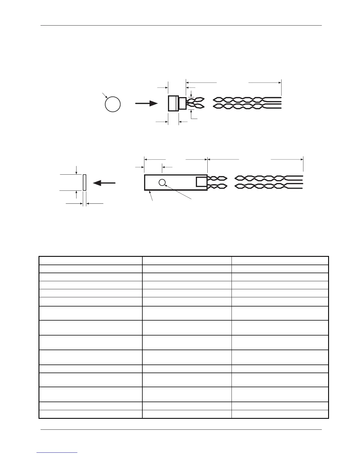
0.105 in.
+B
10 in. (min.)
0.20 in.
0.25 in.
diameter
0.20 in. diameter
C-421-C-5.eps
Figure C-5. Axial Hall Generator HGA-3010, HGA-3030, and HGCA-3020 Dimensions
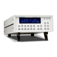
0.240 in.
(max.)
+B
0.63 in.
10 in. (min.)
(Lead Length)
Protective
Ceramic Case
Center of
Active Area
0.180 in.
0.043 in. (max.)
C-421-C-6.eps
Figure C-6. Transverse Hall Generator HGT-3010, HGT-3030, and HGCT-3020 Dimensions
Table C-1. Cryogenic Hall Generator Specifications
Cryogenic HGCA-3020 HGCT-3020
Description Cryogenic axial; phenolic package Cryogenic transverse; ceramic package
Active area (approximate) 0.030 inch diameter circle 0.040 inch diameter circle
Input resistance (approximate) 1 ohm 1 ohm
Output resistance (approximate) 1 ohm 1 ohm
Nominal control current (I
CN
) 100 mA 100 mA
Maximum continuous current
(non-heat sinked)
300 mA 300 mA
Magnetic sensitivity (I
C
= nominal control
current)
0.55 to 1.05 mV/kG 0.55 to 1.05 mV/kG
Maximum linearity error
(sensitivity vs field)
±1.0% RDG (-30 to +30 kG)
±2.0% RDG (-150 to +150 kG)
±1.0% RDG (-30 to +30 kG)
±2.0% RDG (-150 to +150 kG)
Zero field offset voltage (I
C
= nominal
control current)
±200 µV (max.) ±200 µV (max.)
Operating temperature range 4.2 K to 375 K 4.2 K to 375 K
Mean temperature coefficient of magnetic
sensitivity
±0.01%/K (approx.) ±0.01%/K (approx.)
Mean temperature coefficient of offset (I
C
= nominal control current)
±0.4 µV/K (max.) ±0.4 µV/K (max.)
Mean temperature coefficient of resistance ±0.6%/K (max.) ±0.6%/K (max.)
Leads 34 AWG copper w/Teflon insulation 34 AWG copper w/Teflon insulation