Lake Shore Model 421 Gaussmeter User’s Manual
6-4 Service
6.5 REAR PANEL CONNECTOR DEFINITIONS
The connectors on the rear panel of the Model 421 Gaussmeter are detailed in Figures 6-2 thru 6-5.
Additional details for various external serial cables are provided in Paragraphs 6.5 1.
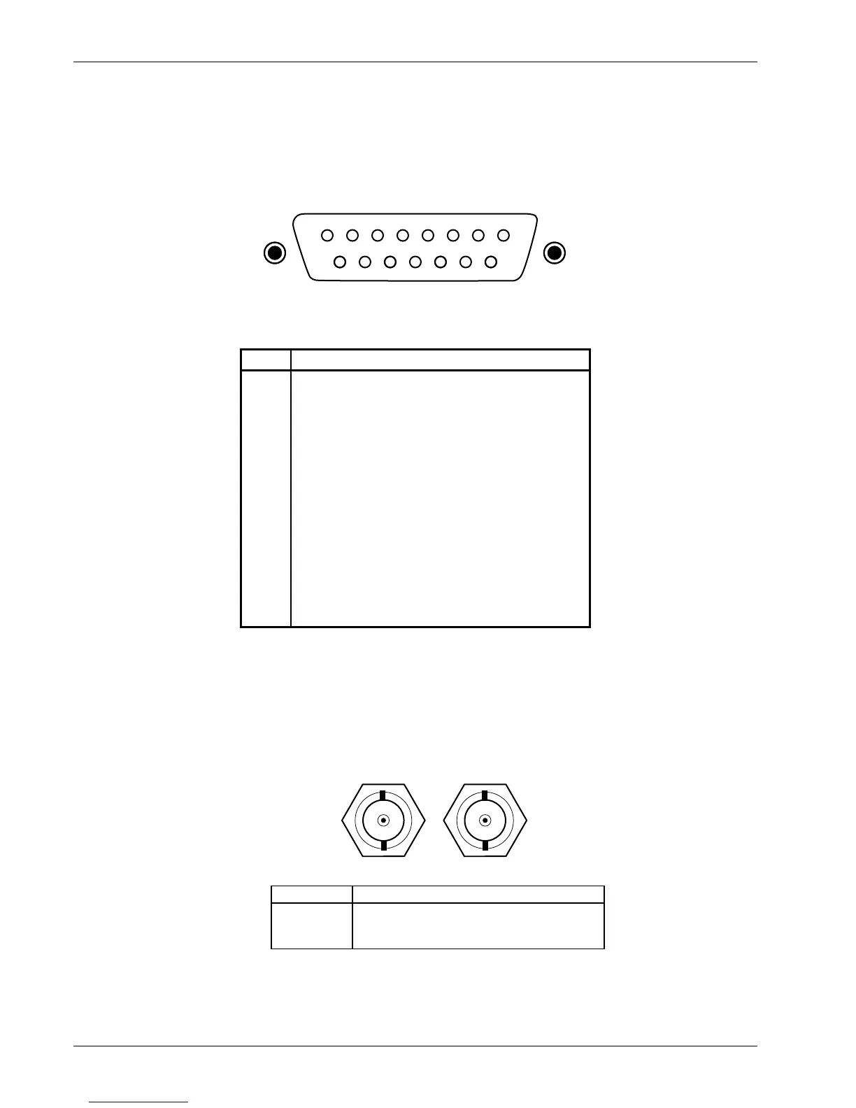
54321
15 14 13 12
PROBE INPUTPROBE INPUT
876
11 10 9
CAUTION: POWER OFF TO MATE PROBECAUTION: POWER OFF TO MATE PROBE
View Looking At Rear
Of Model 421
C-480-6-2.eps
PIN DESCRIPTION
1
2
3
4
5
6
7
8
9
10
11
12
13
14
15
Input + (Analog Signal)
No Connection
No Connection
No Connection
No Connection
No Connection
No Connection
I
C
+
Input - (Analog Signal Ground)
No Connection
Digital Ground
+5 Volts (Power Output To Probe EEPROM)
EE-CLK (Output To Probe EEPROM)
EE-DATA (Serial Input From Probe EEPROM)
I
C
-
Figure 6-2. PROBE INPUT Connector Details
ANALOG OUTPUTSANALOG OUTPUTS
CorrectedCorrected
MonitorMonitor
C-421-6-3.eps
PIN DESCRIPTION
1
2
Analog Output – Center Conductor
Ground – Connector Shell
Figure 6-3. Corrected and Monitor ANALOG OUTPUTS Connector Details