Lake Shore Model 421 Gaussmeter User’s Manual
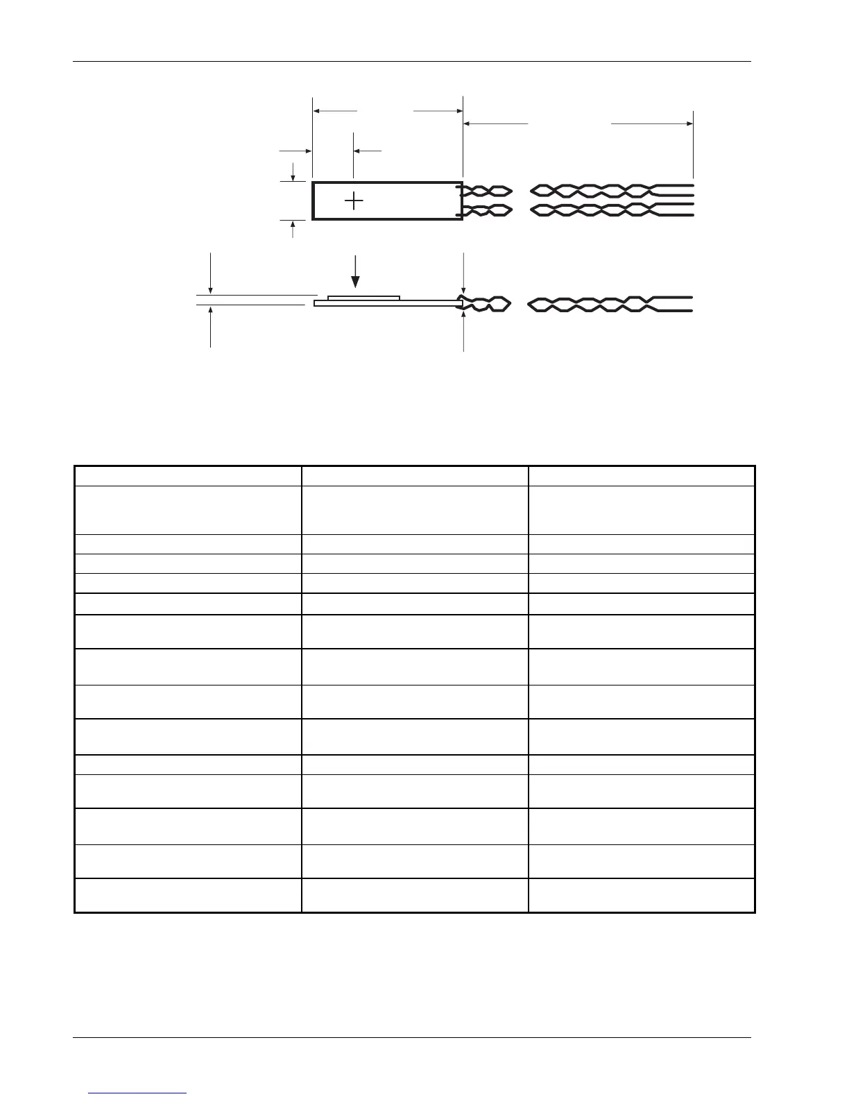
C-6 Hall Generator
0.020 in.
(max.) over
Hall plate
0.130 in. (max.)
+B
0.50 in.
0.125 in.
Center of
Active Area
0.028 in. (max.)
over leads
10 in. (min.)
C-421-C-7.eps
Figure C-7. Transverse Hall Generator HGT-1010 Dimensions
Table C-2. Axial Hall Generator Specifications
Axial HGA-3010 HGA-3030
Description Instrumentation quality axial; low
temperature coefficient; phenolic
package
Instrumentation quality axial; phenolic
package
Active area (approximate) 0.030 inch diameter circle 0.030 inch diameter circle
Input resistance (approximate) 1 ohm 2 ohms
Output resistance (approximate) 1 ohm 2 ohms
Nominal control current (I
CN
) 100 mA 100 mA
Maximum continuous current (non-
heat sinked)
300 mA 300 mA
Magnetic sensitivity (I
C
= nominal
control current)
0.55 to 1.05 mV/kG 6.0 to 10.0 mV/kG
Maximum linearity error (sensitivity
versus field)
±1% RDG (–30 to +30 kG)
±1.5%
RDG (–100 to +100 kG)
±0.30% RDG (–10 to +10 kG)
±1.25% RDG (–30 to +30 kG)
Zero field offset voltage (I
C
= nominal
control current)
±50 µV (max.) ±75 µV (max.)
Operating temperature range –40 to +100 °C –40 to +100 °C
Mean temperature coefficient of
magnetic sensitivity
±0.005%/°C (max.) –0.04%/°C (max.)
Mean temperature coefficient of offset
(I
C
= nominal control current)
±0.4 µV/°C (max.) ±0.3 µV/°C (max.)
Mean temperature coefficient of
resistance
±0.15%/°C (approx.) +0.18%/°C (approx.)
Leads 34 AWG copper with poly-nylon
insulation
34 AWG copper with poly-nylon
insulation