EasyManua.ls Logo

Lakeland CFU139 - User Manual

Lakeland CFU139
2 pages
Print Icon
To Next Page IconTo Next Page
Loading...
CFU139
CEDAR LOG GLIDER
Please check contents before assembly. If any items are missing or damaged, do not take the unit back
to the store. Call 1-800-427-5136 for customer service and we will save you time by correcting any
problems directly for you.
NOTE:
Read all instructions before starting.
Do not completely tighten any screws until the
unit is fully assembled and setting on a level
surface.
Use a rubber mallet (or a block of wood between
the hammer and the unit) to drive doweled ends
into holes as far as possible.
CEAR LOG GLIDER COMPONENTS
LOG GLIDER HARDWARE
(Shown smaller than actual size)
NOTE: Cracks or Checks in logs are part of the natural
beauty of cedar logs and should not be considered defects.
TOOLS REQUIRED
Lay assembled seat on floor. Insert dowel
end of uprights on assembled back into holes
on the back seat rail, adjust uprights in or
out as needed to align properly. Do not tap on
seat back with hammer.
To keep the seat rail from splitting, lay the
back on the floor and drive the seat onto the
dowelled ends by hitting on the bottom of the
seat assembly.
STEP 1
2 Glider End Assemblies
Rail 57” Long
Preassembled Back
6 Braces
9” Long
2 Back Legs
26” Long
2 Arms
20” Long
Preassembled Seat
1 Left
Front Leg
26” Long
1 Right
Front Leg
26” Long
STEP 2
Make a right leg set and a left leg set by
inserting dowel end of back leg into angled hole
of front leg. The drilled holes on each leg should
face the same direction as shown in figure 2.
Put arms onto legs by inserting dowel end of front
legs into the hole in the arms. Drive arm onto leg
assembly as far as possible.
figure 1
figure 2
Question and Answer IconNeed help?

Do you have a question about the Lakeland CFU139 and is the answer not in the manual?

Summary

Cedar Log Glider Components and Hardware

Cedar Log Glider Components

Lists and illustrates the main wooden parts of the glider.

Log Glider Hardware

Details and illustrates the necessary hardware for glider assembly.

Tools Required

Lists the tools needed for assembling the cedar log glider.

Cedar Log Glider Assembly Instructions

Step 1: Attach Back to Seat

Connect the assembled back to the seat rail, ensuring proper alignment.

Step 2: Assemble Legs and Arms

Connect back legs to front legs and attach arms to the leg assemblies.

Step 3: Attach Seat to Leg Sets

Connect the seat assembly to the leg sets and secure with braces.

Step 4: Insert Glider Rail

Insert the glider rail into the glider ends and attach braces.

Step 5: Secure Glider Base

Attach glider straps to the glider base and secure with lag screws.

Step 6: Secure Doweled Joints

Secure the doweled joints on the glider base with flat head screws.

Step 7: Attach Arms to Uprights

Align and secure arms to the uprights using preinstalled lag screws.

Step 8: Attach Seat to Glider Base

Connect the assembled seat to the glider base using glider straps and lag screws.

Step 9: Final Tightening

Firmly tighten all lag screws to complete the glider assembly.

Overview

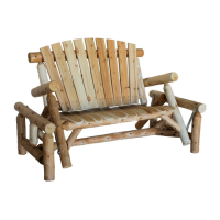
This document provides assembly instructions and a parts list for the Lakeland Mills Cedar Log Glider, model CFU139.

Function Description:

The Cedar Log Glider is an outdoor seating unit designed for relaxation. It features a gliding mechanism that allows the seat to move back and forth smoothly. The construction utilizes cedar logs, which are noted for their natural beauty, including inherent cracks or checks that are considered part of the log's aesthetic.

Important Technical Specifications:

The glider is constructed from various cedar log components, including:

  • Preassembled Back: One unit.
  • Preassembled Seat: One unit.
  • Front Legs: One left (26" long) and one right (26" long).
  • Back Legs: Two (26" long).
  • Arms: Two (20" long).
  • Rail: One (57" long).
  • Braces: Six (9" long).
  • Glider End Assemblies: Two units.

Hardware Components:

  • Lag Screws: Eight 1/4" x 2-1/2" lag screws.
  • Washers: Eight 1/4" washers.
  • Flat Head Screws: Twenty-four 2" flat head screws.
  • Glider Straps: Four (not shown full size in the hardware diagram).

Tools Required for Assembly:

  • Rubber Mallet (or Block of Wood & Hammer)
  • 7/16" Socket (or Wrench)
  • #2 Phillips Screwdriver

Usage Features:

The glider is designed for comfortable outdoor seating with a smooth gliding motion. The assembly process emphasizes proper alignment and secure fastening of all components to ensure safe operation. Users are advised to ensure the unit is fully assembled and setting on a level surface before completely tightening all screws. The design incorporates doweled ends for secure log connections, which should be driven into holes as far as possible using a rubber mallet or a block of wood and hammer.

Assembly Steps:

  1. Seat and Back Assembly: Lay the assembled seat on the floor. Insert the dowel ends of the uprights from the assembled back into the holes on the back seat rail, adjusting as needed. To prevent splitting the seat rail, lay the back on the floor and drive the seat onto the dowelled ends by hitting the bottom of the seat assembly.
  2. Leg and Arm Assembly: Create right and left leg sets by inserting the dowel end of a back leg into the angled hole of a front leg, ensuring drilled holes face the same direction (as shown in Figure 2). Attach arms to the leg sets by inserting the dowel end of the front legs into the arm holes, driving the arm onto the leg assembly as far as possible.
  3. Connecting Seat/Back to Legs: Lay the back and seat assembly on its side. Insert the dowel ends of the seat rail into the holes on the leg sets, driving the legs on as far as possible. Repeat for the other side. Screw a brace onto the seat rail and to the leg, repeating for the other side (as illustrated in Figure 3).
  4. Glider Rail and Strap Attachment: Insert the glider rail into the glider ends, ensuring the rail is off-centered to the back of the glider base. Screw on braces using 2" flat head screws, placing them on the top and front of each end of the glider rail. Attach all four glider straps to the glider base using the 1/4" x 2-1/2" lag screws into pre-drilled holes (as shown in Figure 4).
  5. Securing Glider Base Joints: Turn the glider base on its side. Secure the dowel joint in place with a flat head screw perpendicular to the doweled end (as shown in Figure 5). Repeat for the other end of the glider base.
  6. Final Arm and Leg Fastening: Set the chair in an upright position on a level surface. When the legs are properly positioned, bring the arm against the upright. Tighten the preinstalled lag screws into the pilot hole in the arm using a wrench or socket. Secure doweled joints in place with screws perpendicular to the doweled ends (as shown in Figure 6). Repeat for the other side.
  7. Attaching Seat to Glider Base: Set the assembled seat into the glider base and attach the bottom of the glider strap to the legs of the unit with lag screws in pilot holes (as shown in Figure 7).
  8. Final Tightening: Firmly tighten all lag screws to secure the unit.

Maintenance Features:

  • Pre-assembly Check: Users are instructed to check contents before assembly for any missing or damaged items. If issues arise, contact customer service at 1-800-427-5136 instead of returning the unit to the store.
  • Joint Tightness: All joints should be checked for tightness before and during each usage season to ensure safety and stability.
  • Assembly Accuracy: If hardware is left over after assembly, it indicates incorrect assembly, and the unit may not be safe to use. Customer service should be contacted for assistance.
  • Natural Characteristics: Cracks or checks in the cedar logs are considered part of the natural beauty of the material and should not be regarded as defects.

Lakeland CFU139 Specifications

General IconGeneral
BrandLakeland
ModelCFU139
CategoryIndoor Furnishing
LanguageEnglish