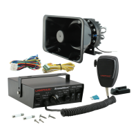
SoundAlert™ - 100W Siren Amplifier with PTT Microphone
IMPORTANT: READ CAREFULLY BEFORE ASSEMBLY AND USE.
Installer of this product must have a good understanding of automotive electronics,
systems, and procedures.
In the case that holes must be drilled in order to properly mount the product, the installer
must examine both sides of the mounting surface before drilling begins. It is the
installer's responsibility to be sure that no vehicle components or vital parts could be
damaged by the drilling process. De-burr any holes in order to remove metal shards and
remnants. Use grommets in all wire passage holes.
If this manual states that this product may be mounted with suction cups, magnets,
tape, or Velcro®, clean the mounting surface and dry thoroughly prior to applying any
adhesives for maximum adhesion.
•
•
•
Do not attempt to activate or operate this product under hazardous driving
situations.
Deployment area of the vehicle air bags must be cleared. Do not install this
product or route any electrical wires near the air bags deployment areas. Refer to
your vehicle owner's manual for the air bag deployment area. Products or wires
mounted in the air bag deployment area will damage, reduce the effectiveness of
the air bag, or even act as a projectile which may cause serious injury or death. The
user/installer of this product assumes full responsibility in determining the proper
mounting location while prioritizing the safety of all passengers in the vehicle.
•
•
DANGER!
Sirens are designed to produce extremely loud emergency warning tones!
Exposure to the tones produced without proper and adequate hearing protec-
tions, could lead to ear damage and/or hearing loss! The Occupational Safety &
Health Administration (www.osha.gov) provides information necessary to
determine safe exposure times in Occupational Noise Exposure Section 1910.95.
The operators of the siren and any one in the immediate vicinity of the siren
should be required to wear an approved hearing protection device until one has
determined the safe exposure times for your specific application. FAILURE TO
FOLLOW THIS RECOMMENDATION COULD CAUSE HEARING LOSS!
Front Panel:
Contents:
True Mods © 2012-2021 All Rights Reserved
CAUTION
Loud Siren noise could
cause damage to
unprotected ears.
Refer to OSHA Section 1910.95 prior
to putting siren into service!
Siren with PTT Mic. 1
Bail Strap Bracket 1
Wiring Bundle 1
Wiring for Horn/Radio 1
Microphone Clip
Mounting Accessories
Fuse(s)
1
1
1
Functions:
Manual Horn/Siren
This switch has two positions. Down – Siren & Up – Horn. The siren and
horn warning tone could be activated manually by engaging the switch
to the positions. Horn function can also be activated with the vehicle
horn relay by connecting the horn/radio wire of the siren unit to the
horn relay of the automobile. (see wiring diagram)
PTT Mic
Push to talk microphone which overrides any activated warning tone
when in use.
Rotary Switch
The rotary knob controls siren functions. There are 5 positions that may
be selected. (see switch functions below for detail)
Speaker/Mic Volume
The volume knob controls the volume of siren and public address
function. Rotating the knob clockwise will increase the volume. Rotat-
ing the knob counter-clockwise will decrease the volume. Rotating the
knob to minimal volume will disable all siren functions.
Aux Switch 1 & 2
The auxiliary switches are meant to be used to power other equipment
on the vehicle. Each auxiliary switch is fused with a 20 amp AGC fuse.
-
-
-
-
-
Manual
Horn/Siren
PTT Mic. Rotary Switch AUX
Switch 1
AUX
Switch 2
Speaker/Mic
Volume
CTRL1VOLUME
MAX.
OFF
SIREN
HORN WAILYELP
RADIO
STAND-BY HI-LO
HI-LO2
CTRL2
www.truemods.com
US Toll Free: 1-855-533-6654
International: 1-909-212-0993
Fax: (909) 575-6722
E-mail: support@truemods.com
Manual ID: PIM-00000067-V002