Do you have a question about the Landis+Gyr E65C Series and is the answer not in the manual?
Records changes and updates to the document over time.
Specifies the communication units covered by this user manual.
Outlines the manual's role in supplementing meter operating instructions.
Defines the intended audience for this user manual.
Lists related technical data and functional description documents.
Details the Landis+Gyr meters compatible with the communication unit.
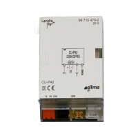
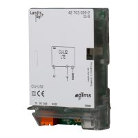
Explains the built-in GSM/GPRS modem and interfaces.
Describes how the communication unit type designation is shown.
Explains GSM and GPRS modem modes and their standards.
Details the CS interface standardization and operation modes.
Describes the RS232 interface and its connection to a PC.
Explains the RS485 interface for connecting multiple meters.
Explains symbols used for danger, warning, and notes.
Outlines the owner's responsibilities for personnel safety.
Lists essential safety regulations for handling the equipment.
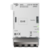
Provides a general view of the unit and its parts.
Details the power supply, antenna, and interface connection points.
Explains the elements and markings on the unit's faceplate.
Describes the function of the four LEDs on the circuit board.
Step-by-step guide for inserting a SIM card into the unit.
Instructions for installing the communication unit into a meter.
Guide for installing the unit within a CU-adapter.
How to connect the antenna cable to the communication unit.
Guidance on selecting the best antenna location for GSM.
Guidance on selecting the best antenna location for GPRS.
Instructions for connecting the CS interface terminals.
How to connect the RS485 interface using RJ12 connectors.
Details on connecting the RS232 interface and converters.
Connecting external 5V power for older meter series.
Connecting external 5V power for Series 3 meters.
Steps to complete after all connections are made.
Procedures for initial setup and verification of operation.
Steps for removing or replacing the communication unit.
Explains LED states for older firmware versions.
Explains LED states for the D72 firmware version.
How to resolve issues with an incorrect SIM card PIN code.
How LEDs indicate the received signal strength.
Guides users through common operational problems.
Procedure for sending the unit for repair.
Process for repairing the integrated 5V power supply.
States that the unit requires no specific maintenance.
Guidelines for proper disposal of electronic waste.
General guidelines for disposal and recycling.
| Brand | Landis+Gyr |
|---|---|
| Model | E65C Series |
| Category | Conference System |
| Language | English |