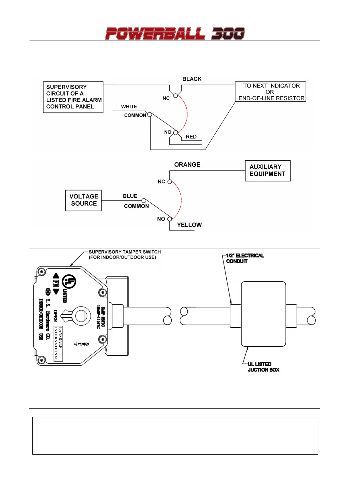
EasyManuals Logo

Lansdale LPBT Series User Manual

Default Icon
4 pages
To Next Page IconTo Next Page
To Previous Page IconTo Previous Page
Page #3 background imageLoading...
Page #3 background image
3
WIRING DIAGRAM
SWITCH SHOWN POSITION WITH VALVE IN FULL OPEN
SWITCH 1 : DUAL LEADS SOLDERED TO SWITCH TABS
SWITCH 2 : SINGLE LEADS SOLDERED TO SWITCH TABS
Green wire is provided as ground for the switch housing.
Switch rating: 10 Amps/ 115 VAC-60Hz, 0.5 Amps/28 VDC
Installation must comply with NFPA 13 and NFPA 72.
Cap unused leads with wire nuts and tuck into a jucntion box (not provided).
Agent:

Questions and Answers:

Question and Answer IconNeed help?

Do you have a question about the Lansdale LPBT Series and is the answer not in the manual?

Lansdale LPBT Series Specifications

General IconGeneral
BrandLansdale
ModelLPBT Series
CategoryControl Unit
LanguageEnglish