EasyManua.ls Logo

Larco Ultra-Small Receiver User Manual

Larco Ultra-Small Receiver
2 pages
To Next Page IconTo Next Page
Page #1 background imageLoading...
Page #1 background image
1902 13th Street SE • PO Box 547 • Brainerd, MN 56401
phone 218-829-9797 • toll free phone 800-523-6996 • fax 218-829-0139 • toll free fax 800-589-3705
www.larcomfg.com
AD14-January 2004
Ultra-Small Receiver Installation
NOTE: Read this manual in its entirety before installing any Larco transmitter or receiver. It is important to complete the
programming procedure before installing the receiver in its final location. The installer must have access to the receiver’s
programming button and must be able to view the receiver’s LED (Light Emitting Diode) during the programming
process.
System
The Larco Ultra-Small Transmitters and Receivers operate at 433.92 MHz (acceptable in the United States, Canada and
any European Union member state) and employ code-hopping technology, to reduce false activations. The receiver only
operates after learning a transmitter’s signal through the simple procedure outlined on the next page. This programming
procedure eliminates the need to set dip switches and involves a simple press of the programming button located on the
top cover of the receiver (see drawings below for details).
Installation
NOTE: Complete the programming
procedure on the next page before
placing the receiver in its final
location.
1. Mount the receiver in a location
so that the antenna is not
surrounded by metal. Metal
attenuates RF signals causing a
reduction in range and
inconsistency of signal reception.
Door operator motors and
controls may also cause radio
frequency interference. Locate
the receiver away from the
door control’s motor(s) and
power supply(s). If the receiver is
mounted in a metal enclosure,
drill a hole in the enclosure and
thread as much of the antenna as
possible through the hole. This
reduces the effects the metal
enclosure will have on the
receiver’s reception.
2. The receiver comes equipped
with a wiring harness for easy
installation. Follow the color-
coding diagram at right.
Diagram 2: Receiver Wiring Harness.
Orange Wire: Normally Open Relay Output
Brown wire with White Stripe: Normally Open Relay Output Common Connection
Red Wire: 24VAC/24VDC Power
Black Wire: Ground
Purple Wire: 12 VDC Power (CAUTION: DO NOT connect 12 VAC Power)
Brown Wire: Normally Closed Relay Output Common Connection
Yellow Wire: Normally Closed Relay Output
Diagram 1: Receiver (left) and Transmitter (right) Dimensional Diagrams
Programming Button
Antenna
See Regulatory Notice on Next Page
Question and Answer IconNeed help?

Do you have a question about the Larco Ultra-Small Receiver and is the answer not in the manual?

Larco Ultra-Small Receiver Specifications

Transmitter

Frequency and Dimensions IconFrequency and Dimensions
frequency433.92 MHz
dimensions1.25” x 0.875” x 0.25”
Battery and Operating Conditions IconBattery and Operating Conditions
battery life60, 000 cycles
operating temperature range-4°F to 122°F (-20°C to 55°C)
security code methodCode Hopping

Receiver

Frequency and Dimensions IconFrequency and Dimensions
frequency433.92 MHz
dimensions2.25” x 1.25” x 0.75”
security code methodCode Hopping
Electrical and Operating Conditions IconElectrical and Operating Conditions
input power24 VAC, 24VDC or 12 VDC
electrical rating100, 000 cycles at 2 Amps at either 24 VDC or 120 VAC
operating temperature range-4°F to 122°F (-20°C to 55°C)
Output and Capacity IconOutput and Capacity
outputTwo Relay Outputs: 1 NO 1 NC
capacityCan learn up to 12 different transmitters
certificationsFCC, Industry Canada, CE

Summary

System Overview

Installation Guide

Receiver Mounting Location

Mount receiver away from metal and interference sources. Drill hole for antenna if in metal enclosure.

Wiring Harness Installation

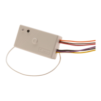
Follow the color-coding diagram for wiring harness installation. Connect wires according to diagram.

Programming Procedures

Programming Transmitters

Learn up to 12 transmitters. Follow steps to program receiver. Repeat for each transmitter.

Setting Output Activation Time

Adjust output activation state from default 1.5 seconds up to 4 hours.

Clearing Transmitter Memory

Clear receiver memory of all learned transmitters. Does not affect output activation time.

Product Specifications

Transmitter Specifications

Details on transmitter frequency, dimensions, security code, battery life, and certifications.

Receiver Specifications

Details on receiver frequency, dimensions, security code, capacity, ratings, and certifications.