6
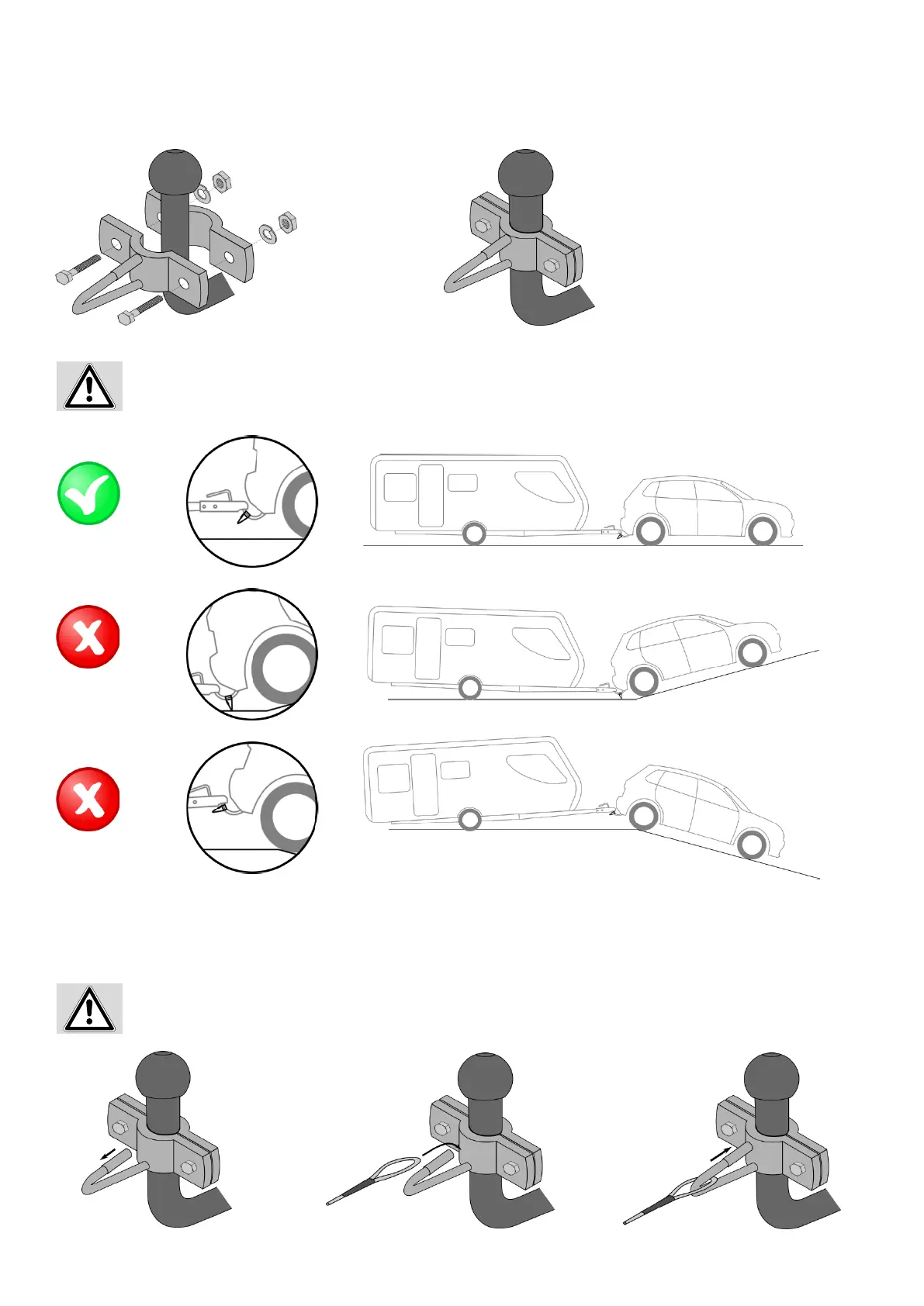
Figure 1: Individual components Figure 2: Holder mounted to coupling neck.
Position the holder for the breakaway cable in such a way on the trailer coupling that there is sucient ground clearan-
ce when traversing dips and also sucient space for the drawbar when going over bumps.
5.2 MOUNTING THE BREAKAWAY CABLE
Figure 3: Pulling back the spring sleeve Figure 4: Mounting the breakaway cable Figure 5: Closing the spring sleeve
Check to make sure that the spring sleeve has closed the holder suciently to ensure that there is no longer a gap that
would enable the breakaway cable to slip out of the holder.
To mount the breakaway cable, pull back on the spring sleeve (Figure 3) and hold securely. Attach the breakaway cable (Figure 4).
Release the spring sleeve (Figure 5).
5. OPERATING INSTRUCTIONS
5.1 INSTALLATION
Mount the holder for the breakaway cable to the trailer coupling of your vehicle in accordance with the diagrams below.