40
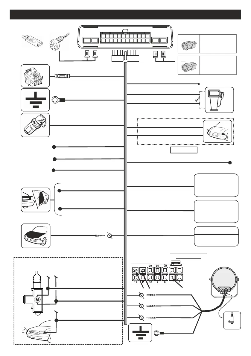
CONNECTION DIAGRAM FOR LC801 ( self-powered)
PURPLE
Ignition key positve
CAN BUS
Signal
RED BROWN- (CAN-L)
Negative signal for ‘hazard’ command
YELLOW-BLACK
R -GR (CAN-H)ED EY
15A
GROUND
BLACK
RED
Engine block
GREEN-BLACK
GREEN
Direction indicator
YELLOW
8A
MAX !
POSITIVE
OR
+12V
KEYLED TXRX
1
12
1324
GREEN-YELLOW
Output for LIN-BUS
special version
WHITE
NEGATIVE OUTPUT
costant with the product
inserted
(status armed)
BROWN-BLUE
NEGATIVE OUTPUT
with the product in alarm
(taken satellite)
Output buzzer
GREY/BLACK
bonnet button
Connection required
only if not managed
from data line or siren
LIGHT BLUE
Analogic button
WHITE-BLUE
Trunk button AUX
pin 7
Signal power in opening
GREEN-BLUE
YELLOW-BLUE
Direction indicator reader
WHITE-ORANGE
Signal power in closing
AP
CH
INDICATORI
DI DIREZIONE
Special connection to make only on the vehicle
not gifted CAN-BUS line.
RED pin 24
BLUE pin 23
White
connector
24-pole
control unit
pin 24
pin 23
Analogic signals present during
the closing and opening of the
vehicle able to arm/disarm
the product (plip)
VOLUMETRIC
PROTECTION
SENSOR
(RED)
VOLUMETRIC
PROTECTION
SENSOR
(WHITE)
Tx
Rx
GREY
908 SIREN
SELF POWRED
SIREN 908
Bonnet button
(optional)
BLACK-Negative
pin 7
GREY pin 7
624-2M630
ORANGE
Socket with
status LED
YELLOW-RED
YELLOW GREY-
Auxiliary alarm and INHIBIT wire
LIN BUS
signal
(with setting)
pin19
pin20
pin21
pin22
pin17
pin18
pin14
pin15
pin16
pin3