49
YELLOW
WHITE-ORANGE
YELLOW-RED
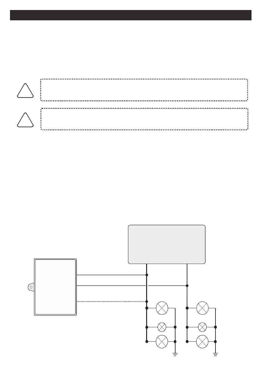
SCHEMATIC CONNECTIONS FOR ARMING/DISARMIG
BY THE DIRECTION INDICATORS
A) CONNECTIONS ON VEHICLES WITH SINGLE WIRE FOR LEFT AND RIGHT
DIRECTION INDICATORS
ANALOGICS SIGNALS OF DIRECTION INDICATORS
(white/orange wire)
ATTENTION THIS CONNECTION IS POSSIBLE ONLY IF THE ORIGINAL RADIO
COMMAND OF THE VEHICLE MAKE FLASHES THE DIRECTION INDICATORS IN
THE OPENING AND CLOSING
The system arming/disarming connection is made by connecting the WHITE-ORANGE
wire to a wire of the direction indicators.
After completing all the electrical connections it’s necessary to make the procedure
‘’SELF-LEARNING OF DIRECTION INDICATORS FLASHES’'
!
!
If the direction indicators are identical during the locking and unlocking,
connect door locking motor unit.
If the direction indicators flash when unlocking with the car mechanical
key, do not make this connection
Main unit
Direction indicators
LEFT
DIRECTION
INDICATORS
RIGHT
DIRECTION
INDICATORS
pin 18
pin 17
pin 11
Connections
alarm
LC80X
WHITE-ORANGE wire must ONLY be
connected if the system operates through
direction indicators
Front
indicator
Rear
indicator
Lateral
indicator
Front
indicator
Rear
indicato
Lateral
indicator
ANALOGIC CONNECTIONS MODE