23
GB
– The transmission signal of the sender should be earthed properly in order to achieve optimal results.
– When working under voltage, be sure to follow the safety instructions.
– The quality of the earth connection greatly affects the range.
!
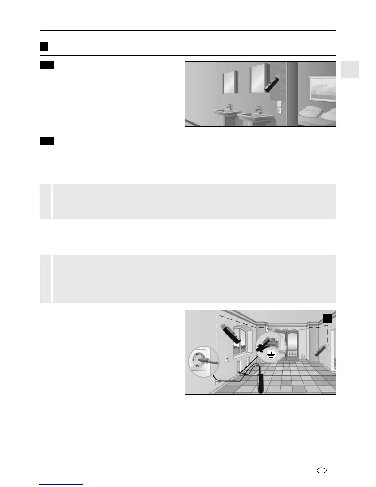
Connect the sender to the cable to be measured
and to the protective earth. See image d in
chapter 6. Then turn on the receiver and begin
searching.
Recommended setting for the receiver: Manual
search mode, maximum sensitivitiy, see chapter
5C.
Tip 1: As an alternative protective earth, you may
use a xed radiator. See image e. However, please
ensure that the radiator is earthed correctly.
Tip 2: A simple way to trace the course of the
cable is to use the acoustic signal, the bar display and the numerical indication on the display. If you need
to record the course of the cable in detail, simply mark those spots where the numerical display indicates
the highest values.
Tip 3: You can increase your range by ve times if you raise the output power of the sender from level 1
to 3.
Tip 4: In order to localise the desired cable further, it may be useful to earth parallel cables as well.
7B-1 Trace cables / locate sockets
Examples for single-pole applications
– Make the measuring circuit zero-potential.
– The lead transmission signal that is fed in may be transmitted to other cables if they are parallel to
the lead over longer distances.
– To expand the range, it is recommended to separate the cable to be measured from the rest of
the measuring circuit.
!
e
7B
Single-pole applications (separate forward and return conductors)
In this case, the sender is only connected to one conductor in a multi-core cable. This conductor then
transmits the high-frequency signal of the sender. The return conductor in this case is the earth, ideally an
earthing conductor or any other good earth connection. The detection depth is a maximum of 2m and is
dependent on the surrounding material.
7
7A
Applications
Voltage detector
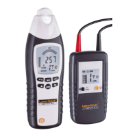
Turn on the receiver and switch to mains voltage
mode. The device will now detect live electric
conductors and can follow their course. The
sender is not necessary for this process. See also
chapter 5A.